Automated generation of local grid refinement at hydraulic fractures for simulation of tight gas reservoirs

a technology of hydraulic fracture and local grid, applied in the field of oil and gas production, can solve the problems of high cost of new well drilling and operating existing wells, low gas production, and significant increase in production over the life of the reservoir, and achieve the effect of reasonable computational complexity and cos

Active Publication Date: 2013-03-21
BP CORP NORTH AMERICA INC
View PDF1 Cites 59 Cited by
  • Summary
  • Abstract
  • Description
  • Claims
  • Application Information

AI Technical Summary

Benefits of technology

[0018]Embodiments provided herein include methods and systems for modeling tight gas reservoirs that permits f

Problems solved by technology

Such optimization is important considering that the costs of drilling of new wells and operating existing wells are high by historical standards, largely because of the extreme depths to which new producing wells must be drilled and because of other physical barriers to discovering and exploiting reservoirs.
Even though a large amount of gas is retained in the earth in these tight formations, the extremely low permeability of these formations results in very low gas production, because the low permeability restricts the rate at which formation gas away from the wellbore can travel to perforations of conventional production wells.
In particular, well spacing in the development of a tight gas field is especially important, given the significant drilling cost typically associated with these reservoirs, and also considering the relative difficulty of obtaining good production from tight gas formations.
In conventional (i.e., non-tight) reservoirs, a single well will produce from a relatively large portion of the reservoir, such that an additional well placed near an existing production well may not significantly increase production over the life of the reservoir.
Some wells may require well treatment, such as additional fracturing of t

Method used


Image

  • Automated generation of local grid refinement at hydraulic fractures for simulation of tight gas reservoirs
  • Automated generation of local grid refinement at hydraulic fractures for simulation of tight gas reservoirs
  • Automated generation of local grid refinement at hydraulic fractures for simulation of tight gas reservoirs

Examples


Embodiment Construction

[0039]This invention will be described in connection with its embodiments, namely as implemented into a computerized system and method of operating the same for modeling and simulating the fluid and pressure behavior of tight gas formations in a production field, as it is contemplated that this invention will be especially beneficial in such an application. It is also contemplated, however, that embodiments of this invention can be beneficially implemented in other situations and applications. Accordingly, it is to be understood that the following description is provided by way of example only, and is not intended to limit the true scope of this invention as claimed.

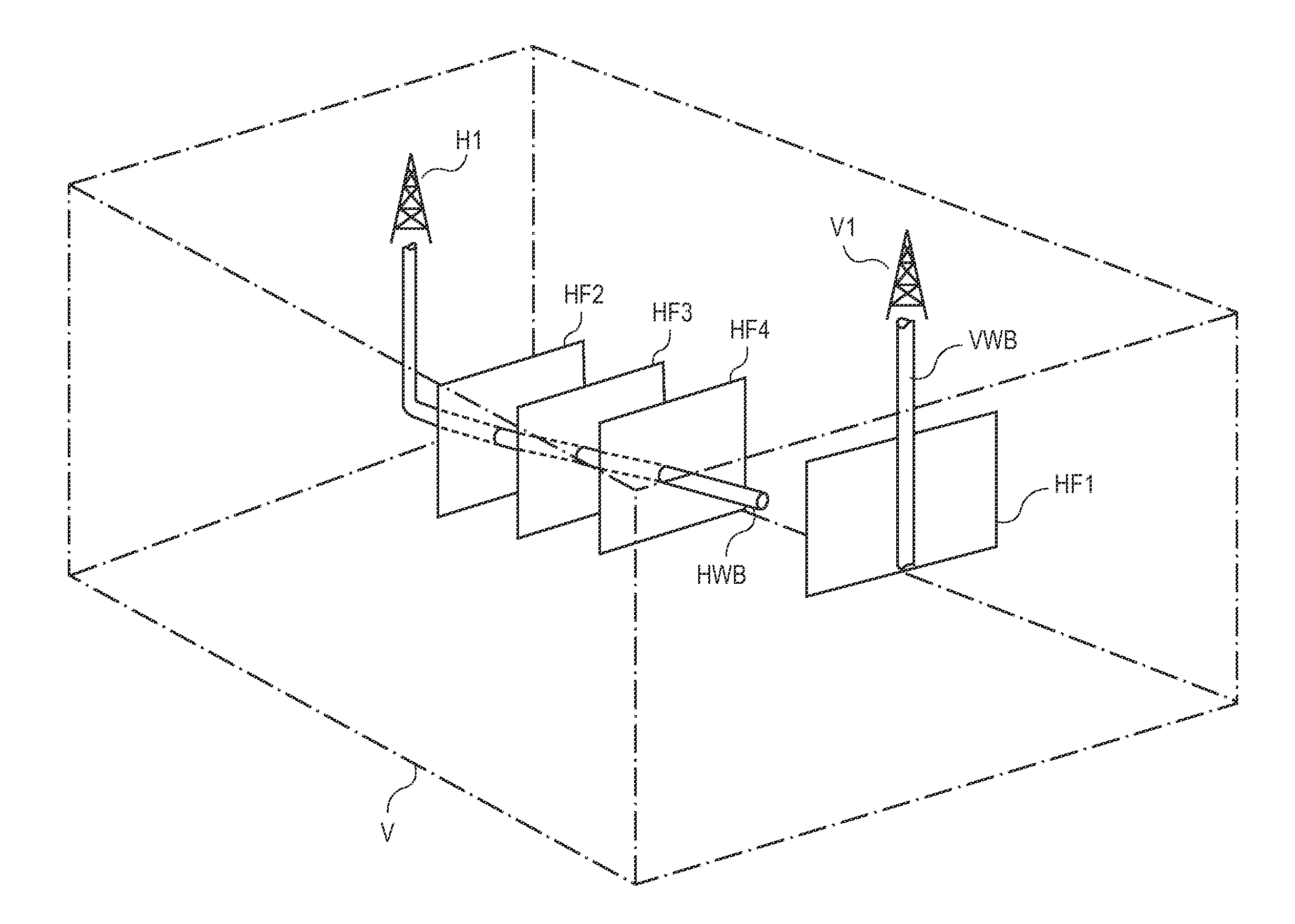
[0040]FIG. 1 illustrates, in a simplified manner, volume V of the sub-surface of the earth, into which two gas wells H1, V1 are deployed. While not shown in FIG. 1, multiple sub-surface strata, or formations, are present within the volume, of varying composition, thickness, and location, depending on the geology and geol...


PUM


Abstract

A computer system and method of automatically generating a Local Grid Refinement (LGR) gridded model of a gas reservoir. A geologic file includes information identifying the locations of one or more wells according to root grid cells within a volume of the earth to be modeled. User inputs specify the number of hydraulic fractures from each well, and such parameters as the fracture length, etc. User inputs also specify the number of “splits” of the root grid cells containing hydraulic fractures; those root grid cells are then split into finer resolution grid cells of increasing width within the root grid cells containing the fractures. For horizontal wells, user inputs indicate the number of splits of root grid cells containing the lateral portions of the wellbore. Non-orthogonal and complex fractures are processed by a“nested” LGR approach. Geologic properties are assigned to each grid cell, with a tensorial adjustment included for non-orthogonal fractures, and the resulting model is available for simulation.

Description

CROSS-REFERENCE TO RELATED APPLICATIONS[0001]This application claims priority, under 35 U.S.C. §119(e), of U.S. Provisional Application No. 61 / 536,943, filed Sep. 20, 2011, incorporated herein by reference in its entirety for all purposes.STATEMENT REGARDING FEDERALLY SPONSORED RESEARCH OR DEVELOPMENT[0002]Not applicable.BACKGROUND[0003]This invention is in the field of oil and gas production. Embodiments of this invention are more specifically directed to the production performance analysis of wells for purposes of well and reservoir management.[0004]The current economic climate emphasizes the need for optimizing hydrocarbon production. Such optimization is important considering that the costs of drilling of new wells and operating existing wells are high by historical standards, largely because of the extreme depths to which new producing wells must be drilled and because of other physical barriers to discovering and exploiting reservoirs. These high economic stakes demand operato...

Claims


Application Information

Patent Timeline
IPC IPC(8): E21B41/00G06F17/10
CPCE21B41/0092G01V11/00G06F17/10G06F30/20
Inventor ABACIOGLU, YAFESATES, HARUNSEBASTIAN, HERBERT
Owner BP CORP NORTH AMERICA INC
Why Eureka
Try Eureka