Vehicle-carried Air Compression Device

a technology for compressed air and vehicles, applied in vehicle maintenance, transportation and packaging, vehicle servicing/repairing, etc., can solve problems such as contamination of users or other objects

Active Publication Date: 2013-05-02
UNIK WORLD IND CO LTD
View PDF6 Cites 44 Cited by
  • Summary
  • Abstract
  • Description
  • Claims
  • Application Information

AI Technical Summary

Benefits of technology

[0005]Thus, an objective of the present invention is to provide a vehicle-carried air compression device to improve the aforementioned problems. The air compression device of the present invention can be used for rescue works of air inflation and tire sealing up, and a liquid adhesive in a tire repairing container will not shoot out suddenly because of improper handling.
[0006]To achieve this and other objectives, a vehicle-carried air compression device of the present invention includes a case having an air compressor therein, a tire repairing container containing a liquid adhesive for sealing automobile tires, and a flexible linking tube including a first end combined with a connector and a second end provided with a protection adapter. The tire repairing container includes an adhesive outlet coupler and an air inlet coupler connected with the air compressor. The connector is coupled to the adhesive outlet coupler of the tire repairing container. The protection adapter is adapted to be connected with an air nipple of a tire and includes an outer cover, a base, a buffer ring, a valve cock, and a spring. The outer cover has an axial hole extending through the outer cover and including a first end having an opening and a second end having a coupling portion for connecting with the air nipple of the tire. A shoulder is formed on an inner end surface of the coupling portion. The base includes a connecting section and a cylindrical section with a cylindrical chamber therein. The cylindrical section of the base is received in the axial hole of the outer cover from the opening, and the connecting section is protruded outside of the opening of the outer cover. A passage is formed in the connecting section and in communication with the cylindrical chamber. The buffer ring is mounted in the cylindrical section of the base and has a through-hole extending through the buffer ring. A flange is formed on an end of the buffer ring and pressed against the shoulder of the outer cover. The valve cock is received in the cylindrical chamber of the base and includes a pole body extending through the through-hole of the buffer ring and a head extending outwardly from an end of the pole body. The spring is sleeved around an outer circumference of the head of the valve cock and received in the cylindrical chamber of the base. The spring biases the valve cock towards the buffer ring to close the through-hole of the buffer ring. When the air nipple of the tire is engaged with the coupling portion of the outer cover, the air nipple is in contact with the valve cock and moves the valve cock away from the buffer ring, so that the spring is compressed to open the through-hole of the buffer ring. Before the tire nipple is connected with the protection adapter of the flexible linking tube, the flexible linking tube is closed by the protection adapter, so that the liquid adhesive in the tire repairing container will not shoot out suddenly because of improper handling.

Problems solved by technology

However, during the process of mending or sealing with the liquid adhesive, if a power source is connected under conditions that a user did not notice a power switch status of the case is ON (the power switch of the case may be switched to ON status) and the user has not connected the flexible linking tube to the air nipple of the tire, then the liquid adhesive in the tire repairing container will shoot out suddenly from the other end of the flexible linking tube, and the user or other articles will get contaminated.

Method used


Image

  • Vehicle-carried Air Compression Device
  • Vehicle-carried Air Compression Device
  • Vehicle-carried Air Compression Device

Examples


Embodiment Construction

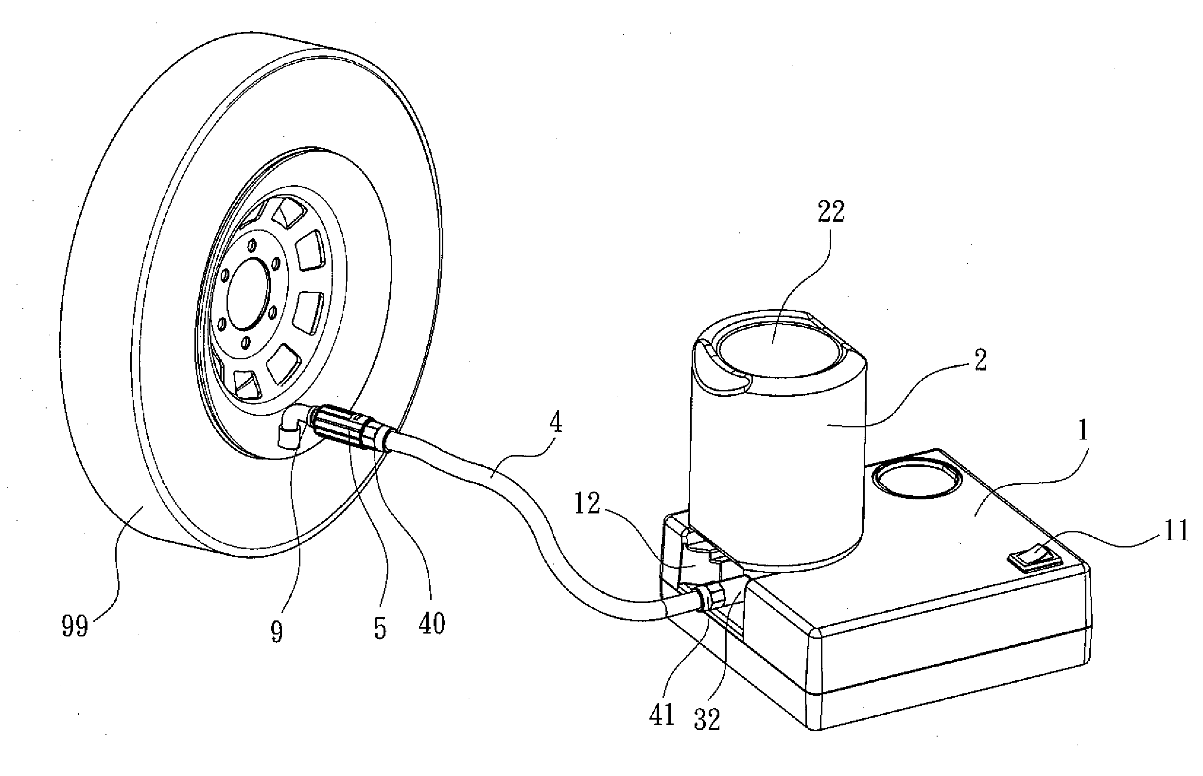
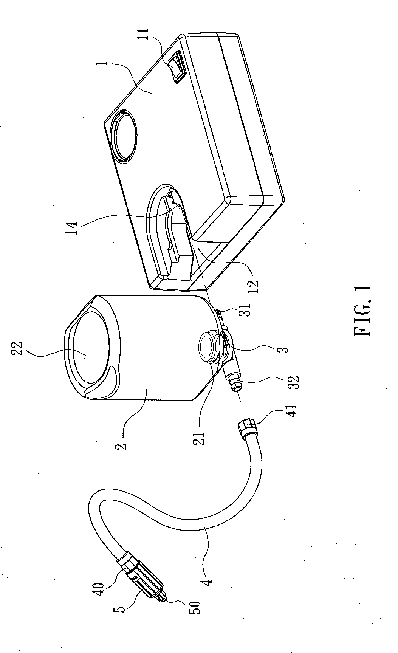
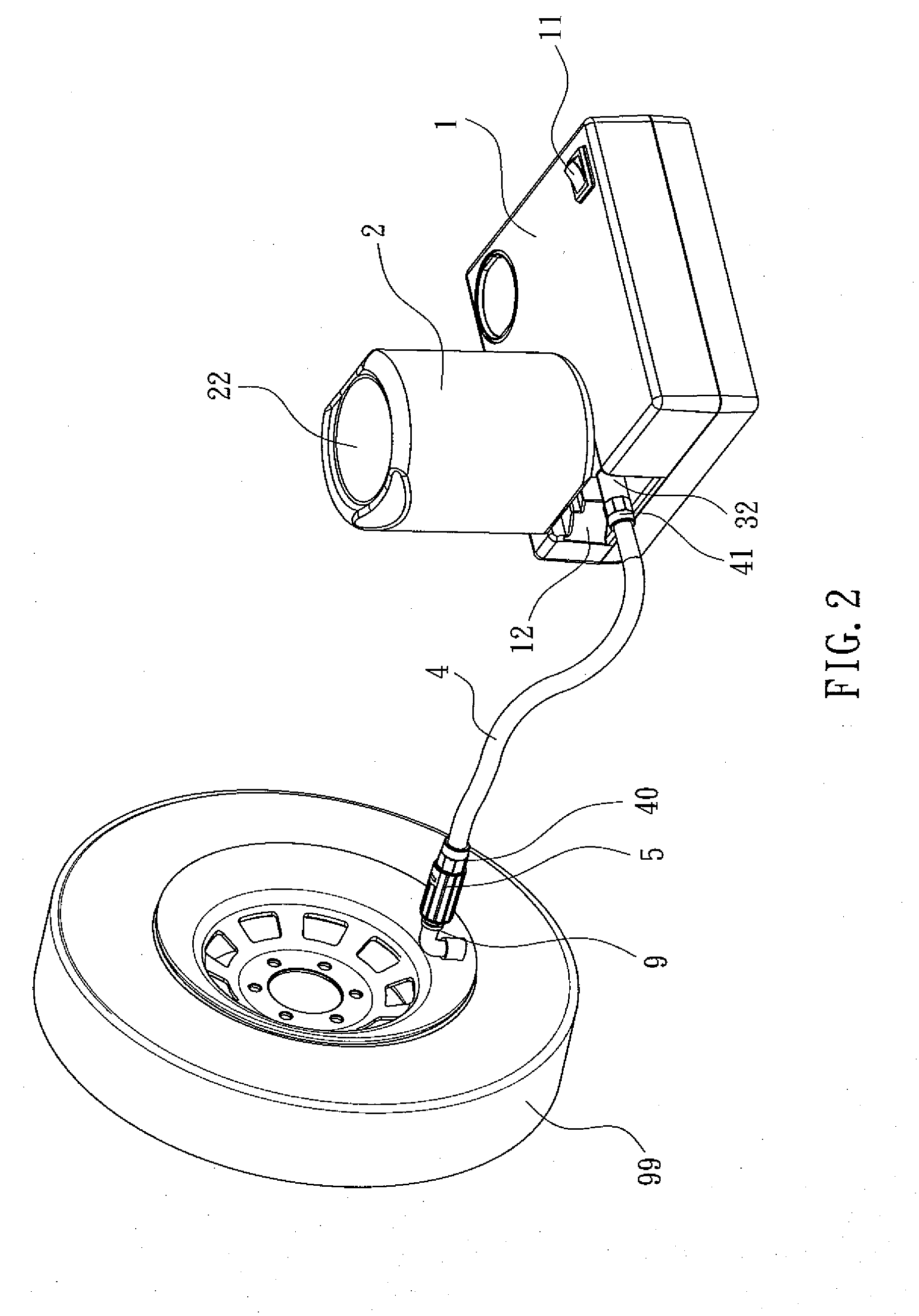
[0021]FIG. 1 shows an air compression device of the present invention applicable to be carried in an automobile to perform rescue works of repair and inflation for a damaged tire 99 (see FIG. 2). The air compression device includes a case 1, a tire repairing container 2, and a flexible linking tube 4.

[0022]Referring to FIGS. 1 to 10, the case 1 includes a switch 11 thereon and a coupling indentation 12 therein. An air compressor 13 is installed inside the case 1 and includes an air outlet manifold 14 having an end in the coupling indentation 12. The tire repairing container 2 has an opening 21 disposed at a side opposite to a bottom wall 22 of the tire repairing container 2 and screwed together with a lid 3. An air inlet coupler 31 and an adhesive outlet coupler 32 are provided on the lid 3. The tire repairing container 2 is engaged to the coupling indentation 12 of the case 1 with the opening 21 pointing downward and with the air inlet coupler 31 of the lid 3 connected to the air o...


PUM

PropertyMeasurementUnit
flexibleaaaaaaaaaa
outer circumferenceaaaaaaaaaa
circumferenceaaaaaaaaaa

Abstract

A vehicle-carried air compression device includes a case installed with an air compressor therein, a tire repairing container containing a liquid adhesive, and a flexible linking tube. An air inlet coupler of the tire repairing container is connected with an air outlet manifold of the air compressor. An end of the flexible linking tube is coupled to an adhesive outlet coupler of the tire repairing container, and the other end of the flexible linking tube is combined with a protection adapter for coupling to a tire nipple. Before the protection adapter is connected with the tire nipple, the other end of the flexible linking tube is closed by the protection adapter, so that the liquid adhesive in the tire repairing container will not shoot out suddenly because of improper handling.

Description

BACKGROUND OF THE INVENTION[0001]1. Field of the Invention[0002]The present invention relates to an air compression device and, more particularly, to a vehicle-carried air compression device which can mend or seal damaged tires with an adhesive or a puncture-sealing agent and inflate them.[0003]2. Description of the Related Art[0004]A conventional air compressing apparatus for repairing and inflating damaged tires includes a case installed with an air compressor therein and a tire repairing container containing a liquid adhesive or puncture-sealing agent. An air inlet coupler and an adhesive outlet coupler are disposed on the tire repairing container. A conduit is connected between the air inlet coupler and an air outlet manifold of the air compressor. The adhesive outlet coupler is connected to an end of a flexible linking tube, and the other end of the flexible linking tube is adapted to be connected to an air nipple of a damaged tire. When the flexible linking tube is connected t...

Claims


Application Information

Patent Timeline
Patent Type & Authority Applications(United States)
IPC IPC(8): B60C23/10
CPCB29C73/166B60S5/043Y10T137/3724Y10T137/7837
Inventor CHOU, WEN-SAN
Owner UNIK WORLD IND CO LTD
Why Eureka
Try Eureka