Rolling bearing unit for supporting a wheel with an air compressor

a technology of roller bearings and air compressors, which is applied in the direction of machines/engines, positive displacement liquid engines, pumping machines, etc., can solve the problems of uneven air pressure, increased leaking from the valve section of the air supply section, and uneven air pressure, so as to increase the overall capacity of the cylinder or cylinder. , the effect of keeping the resistance against the rotation of the hub low

Active Publication Date: 2008-01-10
NSK LTD
View PDF22 Cites 32 Cited by
  • Summary
  • Abstract
  • Description
  • Claims
  • Application Information

AI Technical Summary

Benefits of technology

[0048]The wheel-supporting roller-bearing unit with air compressor of this invention is compact and is capable of keeping the resistance against the rotation of the hub low while at the same time maintaining good balance.
[0049]Furthermore, when necessary, it is capable of obtaining compressed air having sufficient pressure regardless of the traveling speed of the vehicle. In other words, in the embodiment of the invention in which a plurality of cylinder holes or cylinders are located at a plurality of locations evenly spaced in the circumferential direction, it is possible to increase the overall capacity of the cylinder holes or cylinders even though the capacity of each cylinder hole or cylinder is decreased, and thus it is possible to maintain the required amount of compressed air that is obtained during one rotation of the hub.
[0050]Also, the instant when the force required to displace the pistons inside the cylinder holes or cylinders in the axial direction becomes large shifts in the rotational direction of the hub for each individual cylinder hole or cylinder. Therefore, it is possible to keep the amount that the resistance against the rotation of the hub fluctuates due to the rotation position of the hub low, and it is possible to keep this resistance low with good balance.
[0051]Also, in the construction of this embodiment, compressed air is generated by a reciprocating-piston air compressor, so unlike in the case of a rotary or scroll compressor, the pressure of the obtained compressed air is constant and not affected by the rotation speed of the hub. The amount of discharge is proportional to the rotation speed of the hub. Therefore, it is possible to obtain compressed air with steady pressure regardless of fluctuation in the traveling speed of the vehicle.
[0052]Moreover, individual cylinder holes or cylinders are compact, so it becomes easy to design the cylinder holes or cylinders so that they can be installed in the limited space inside or near the wheel-supporting roller-bearing unit, and thus it is possible to make a compact and lightweight wheel-supporting roller-bearing unit with air compressor.
[0053]The wheel-supporting roller-bearing unit with air compressor becomes the so-called unsprung load that exists further on the road side than a spring which constitute the suspension apparatus, so making the construction lightweight helps in maintaining the driving performance, such as the riding comfort and driving stability, of the vehicle.

Problems solved by technology

There is a proper value for the air-pressure in the tires of automobile wheels, however, this air pressure gradually decreases due to leaking and varies due to the outside air temperature.
In other words, the gas barrier of the rubber material of the tires is not perfect, and there is also a possibility that leaking from the valve section of the air-supply section may become greater than leaking through the rubber material.
However, except for the case of commercial vehicles such as trucks, busses, taxis and the like, there are very few drivers who constantly check the air pressure.
The reason for this is that the air pressure of each of the wheels will decrease somewhat due to leaking that occurs until the next required vehicle inspection, and this is thought to make it more difficult for dangerous conditions such as bursting to occur when driving at high speed even though the driver does not maintain the air pressure.
However, in this situation, the air pressure of each of the wheels is set higher than the proper value, which together with making riding comfort of the automobile poor, adversely affects driving stability and brake performance of the automobile.
Particularly, this tendency becomes more severe when regular vehicle inspection is performed in a season such as the beginning of spring when the outside temperature begins to increase.
In recent years, leakage of air is kept to a minimum by changing the gas used to fill the wheels from air to nitrogen gas that does not contain other gasses such as oxygen; however, it is still difficult to completely eliminate leaking.
However, even when the air pressure has been set lower for driving on a poor road, when driving particularly at high speed on a good paved road after that, the air pressure must be increased, so it is necessary to fill each of the wheels with air.
Moreover, the same problem occurs when considering that the wheels must be filled with air again after the temperature has decreased after lowering the air pressure of the wheels that has greatly increased due to rising temperature when driving during the summer.
However, having to stop the car to fill the wheels with air with a separate air compressor every time the road conditions change, or every time the driving conditions or temperature changes is not practical.
In order to always maintain the air pressure in the tires at a proper pressure, it is necessary to maintain the seal of this air-supply path even after use over a long period of time, which results in increased cost.
From the aspect of maintaining the driving stability of an automobile in which this kind of wheel-supporting roller-bearing unit with air compressor is installed, this kind of condition is not desirable.

Method used


Image

  • Rolling bearing unit for supporting a wheel with an air compressor
  • Rolling bearing unit for supporting a wheel with an air compressor
  • Rolling bearing unit for supporting a wheel with an air compressor

Examples


first example

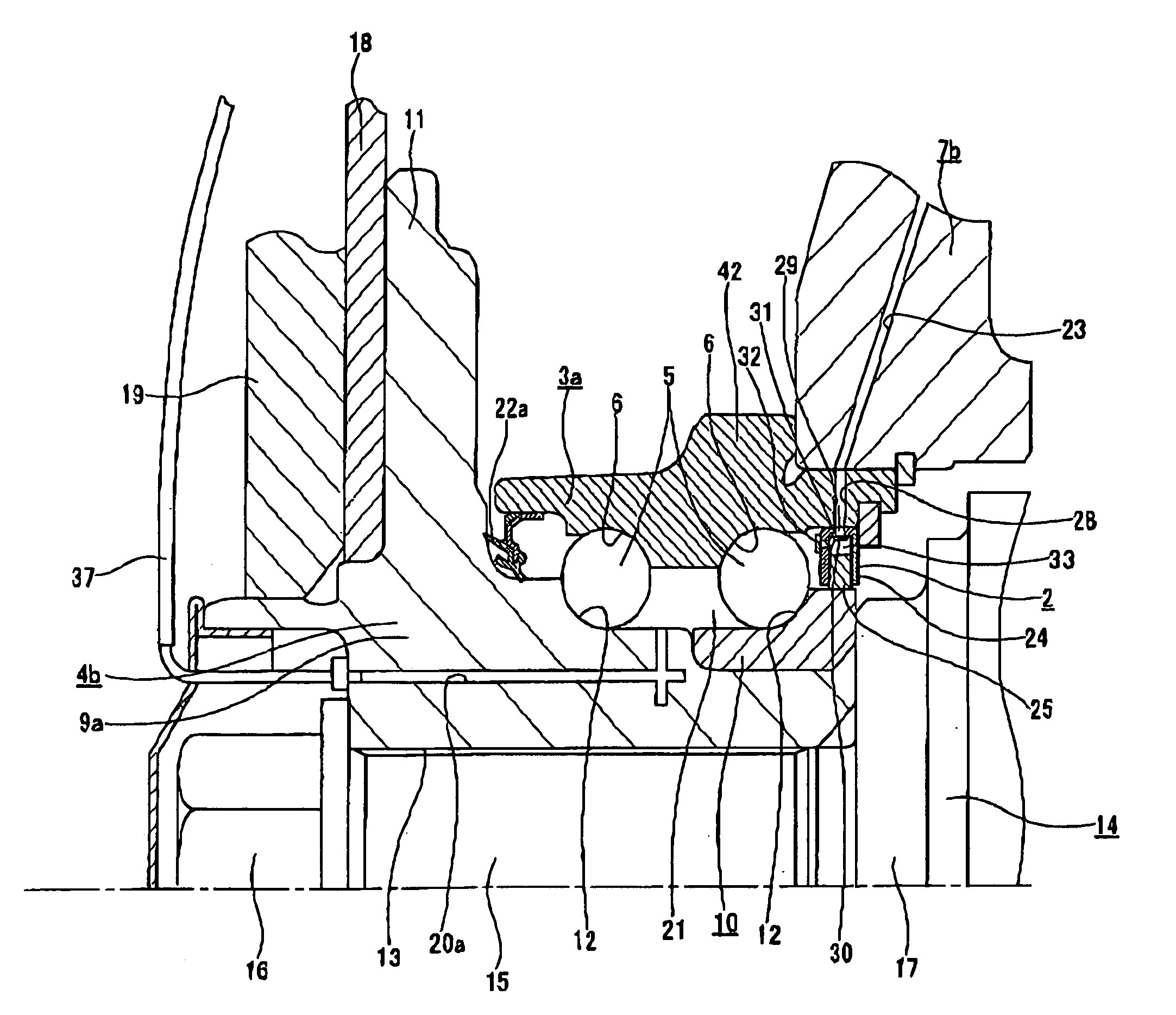
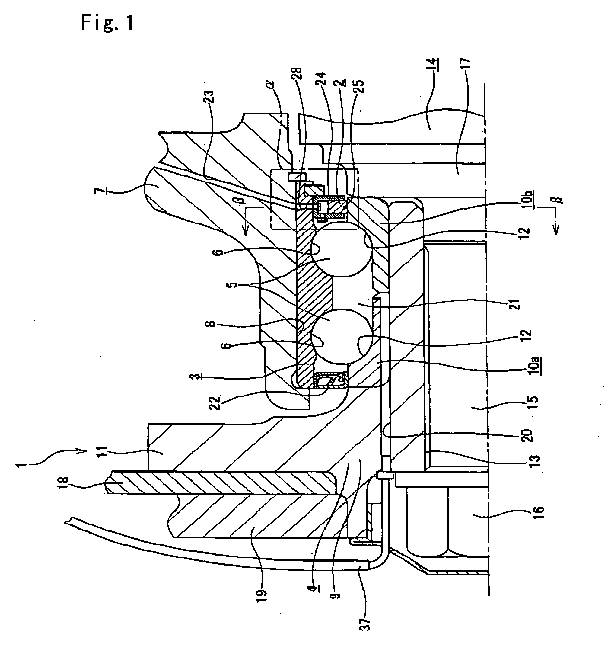
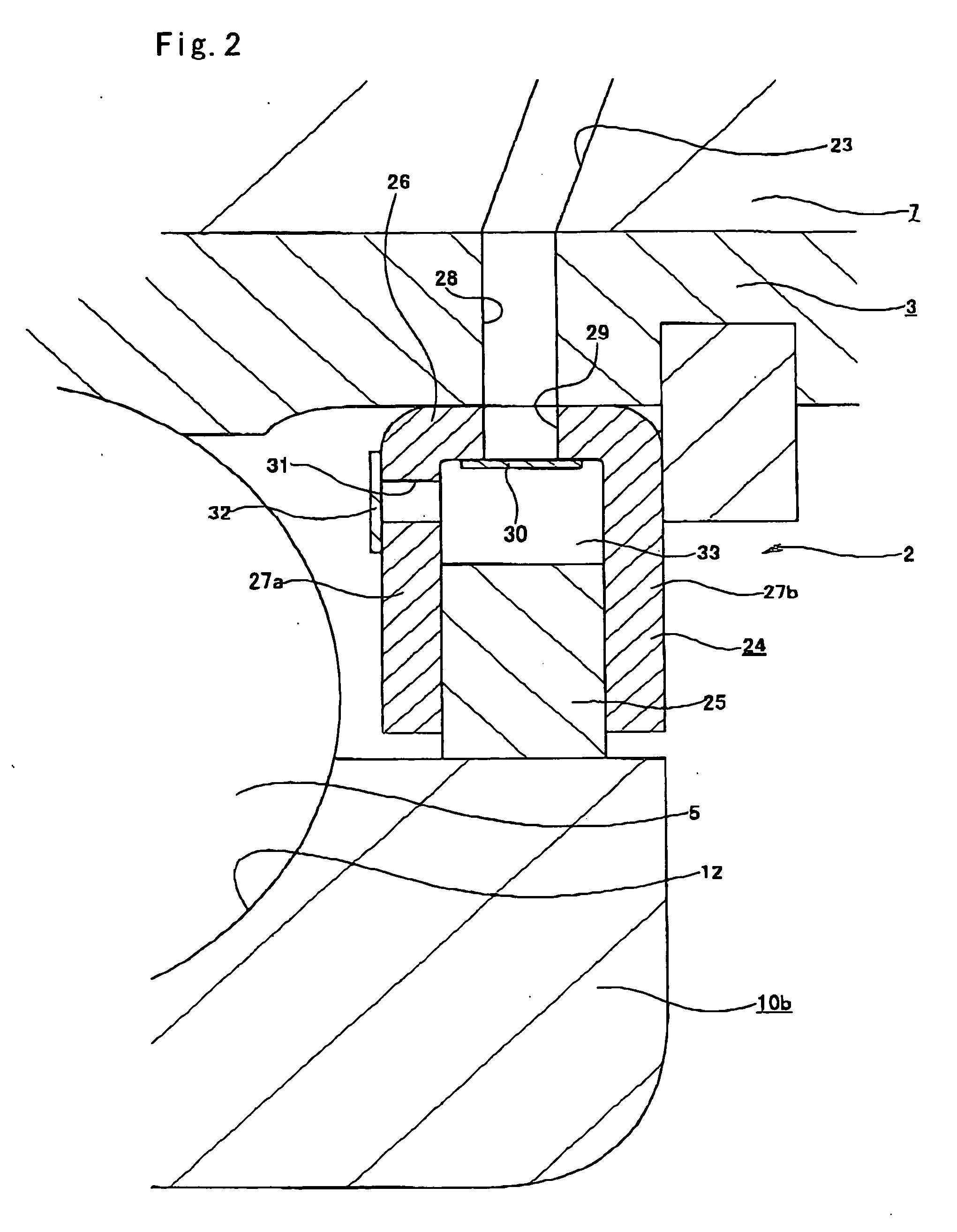
[0089]FIGS. 1 to 4 show a first example of the invention. The wheel-supporting roller-bearing unit with air compressor of this example comprises a rotary air compressor 2 that is installed on the inside end in the axial direction of a wheel-supporting roller-bearing unit 1. Of these, the wheel-supporting roller-bearing unit 1 comprises an outer ring 3, hub 4 and a plurality of rolling elements 5. Of these, the outer ring 3 is formed so that there is a double row of outer raceways 6 formed around its inner peripheral surface, and so that the outer peripheral surface has a cylindrical surface shape. During use, this kind of outer ring 3 is fitted into the support hole 8 of the knuckle 7 of the suspension apparatus and does not rotate, and it is positioned in the axial direction by being held from both sides in the axial direction between a rim section and retaining ring. Here, inside in the axial direction means the side that is toward the middle in the width direction of the vehicle ...

second example

[0098]FIGS. 5A and 5B show a second example of the present invention. In this example, there is an eccentric ring 38 located between the outer peripheral surface of the inner ring 10b of the hub 4 and the inner peripheral surface of the rotor 25. Similar to the rotor 25, this eccentric ring 38 has a circular ring shape with a rectangular cross section, and the center axis of the outer peripheral surface is parallel to but eccentric with the center axis of the inner peripheral surface. The amount of eccentricity between the inner and outer peripheral surfaces of the eccentric ring 38 is the same as the amount of eccentricity between the inner and outer peripheral surfaces of the rotor 25. Also, a driving mechanism, such as an ultrasonic motor, is located between the inner peripheral surface of the rotor 25 and the outer peripheral surface of the eccentric ring 38 for driving and rotating the rotor 25 with respect to this eccentric ring 38 by a vibrating element such as a piezo elemen...

third example

[0100]FIG. 6 shows a third example of the present invention. In this example, opposite to that of the first and second examples described above, the member corresponding to the inner ring is taken to be the stationary ring. Also, the wheel that is supported by the wheel-supporting roller-bearing unit 1a so that it rotates freely is an undriven wheel. Therefore, in the case of this example a pair of inner rings 10a, 10b are fitted onto the shaft section 39 on part of the knuckle 7a of the suspension apparatus and fastened by a nut 16. Moreover, surrounding both of these inner rings 10a, 10b is the hub 4a, which is the member corresponding to the outer ring, and it rotates together with the wheel 19 and brake rotating member 18, and is supported by a plurality of rolling elements 5 so that it can rotate freely.

[0101]In the case of this example, the construction of the air compressor 2a is such that the inside and outside in the radial direction are opposite that of the first and secon...


PUM


Abstract

A wheel-supporting roller-bearing unit with air compressor that is compact and capable of keeping resistance against the rotation of the hub 4c low while at the same time maintaining good balance, and when necessary, is capable of obtaining compressed air having sufficient pressure regardless of the traveling speed of the vehicle. A plurality of cylinder holes 53 are located at a plurality of locations that are evenly spaced around the circumferential direction on the inside of a cylinder block 50 that is connected and fastened to the inside end section in the axial direction of the hub 4c. Pistons 54 fit inside these cylinder holes 53 and are moved back and forth by a piston-drive mechanism 62 as the cylinder block 50 rotates. The air compressor 2c is a reciprocating-piston compressor, so it is possible to obtain the required air pressure regardless of rpm. Also, by placing a plurality of cylinder holes 53 and pistons 54 at uniform intervals around in the circumferential direction, it is possible to suppress the resistance against the rotation of the hub 4c.

Description

BACKGROUND OF THE INVENTION[0001]1. Field of the Invention[0002]This invention relates to a wheel-supporting roller-bearing unit with air compressor, which is used for supporting an automobile wheel so that it can rotate freely with respect to the suspension apparatus, and that properly maintains air pressure in the tires of the wheel.[0003]2. Description of the Prior Art[0004]There is a proper value for the air-pressure in the tires of automobile wheels, however, this air pressure gradually decreases due to leaking and varies due to the outside air temperature. In other words, the gas barrier of the rubber material of the tires is not perfect, and there is also a possibility that leaking from the valve section of the air-supply section may become greater than leaking through the rubber material. Moreover, as is clear from Boyle's Law and Charles's Law, even when leakage is ignored, the air pressure fluctuates 10% or more in the summer and winter, even though the rise in temperature...

Claims


Application Information

Patent Timeline
Patent Type & Authority Applications(United States)
IPC IPC(8): B60C29/00
CPCF16C19/184F16C41/00F16C41/005B60C23/004B60C23/12F16C33/723F16C2326/02F16C2360/42B60C23/127B60C23/137
Inventor WAKABAYASHI, TATSUOKANAYAMA, YOSHIHIRO
Owner NSK LTD
Why Eureka
Try Eureka