Hierarchical sensing method

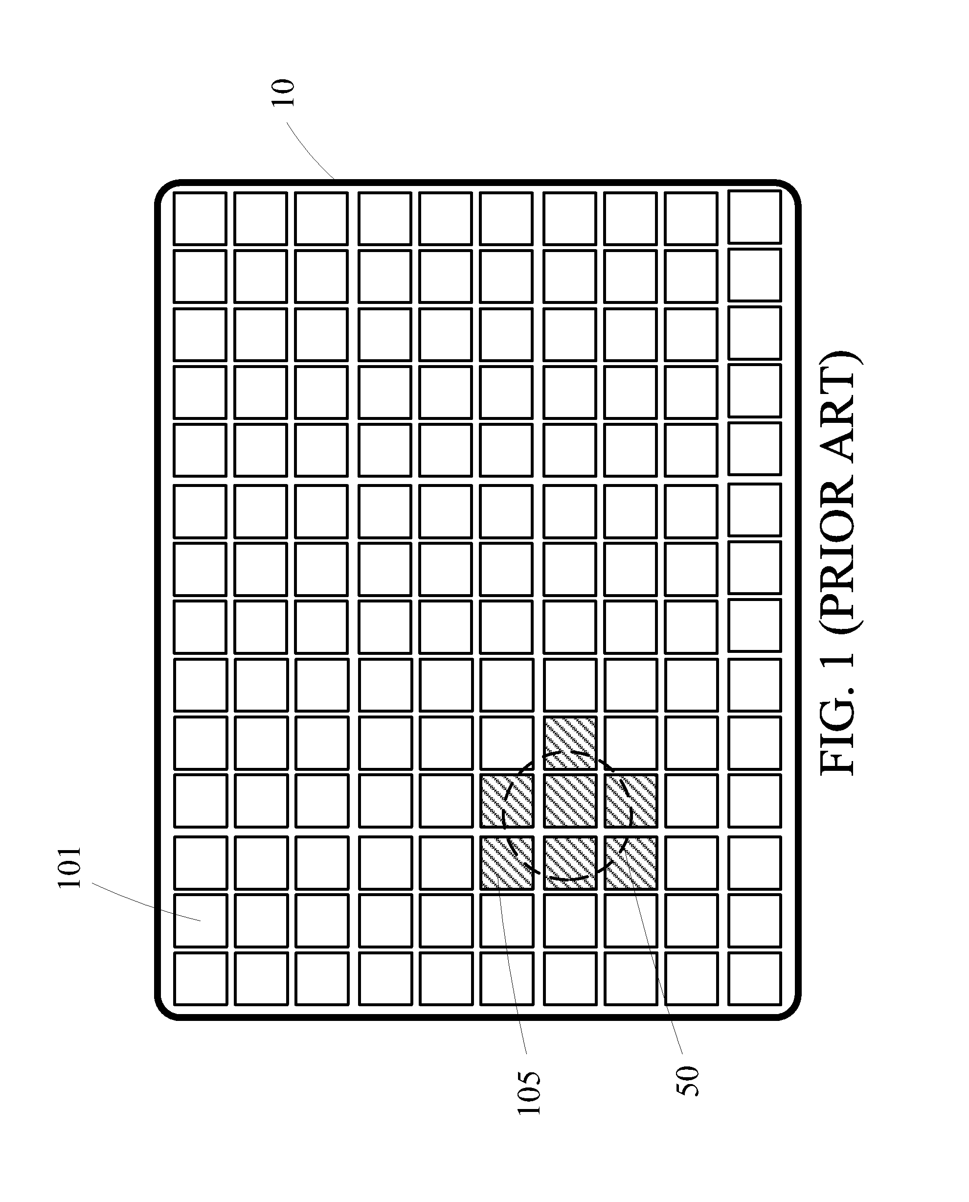
a sensing method and hierarchy technology, applied in the field of touch sensing technique, can solve the problems of insufficient speed response a touch or touch to the touch panel b>10/b>, waste of time in scanning unnecessary points, etc., and achieve the effect of improving sensing speed, greater accuracy, and faster sensing speed

Inactive Publication Date: 2013-05-02
SILICON INTEGRATED SYSTEMS
View PDF4 Cites 2 Cited by
  • Summary
  • Abstract
  • Description
  • Claims
  • Application Information

AI Technical Summary

Benefits of technology

[0006]An objective of the present invention is to provide a hierarchical sensing method, which is capable of improving sensing speed as well as greater accuracy.
[0007]In accordance with an aspect of the present invention, a hierarchical sensing method for a touch panel having a matrix of points for detecting a touch or touches comprises: dividing the points into a plurality of blocks; selecting several points in each one of the blocks as designated points; sensing first data from each one of the designated points; determining a set of possible touched points according to the first data sensed from each one of the designated points; sensing second data from the set of possible touched points; and determining if each one of the possible touched points is an actual touched point according to the second data sensed from said one possible touched point. By using the method of the present invention, faster sensing speed and greater sensing accuracy can be achieved.

Problems solved by technology

However, much time is wasted to scan unnecessary points, and as a result, the speed responding a touch or touches to the touch panel 10 is not fast enough.

Method used


Image

  • Hierarchical sensing method
  • Hierarchical sensing method
  • Hierarchical sensing method

Examples


first embodiment

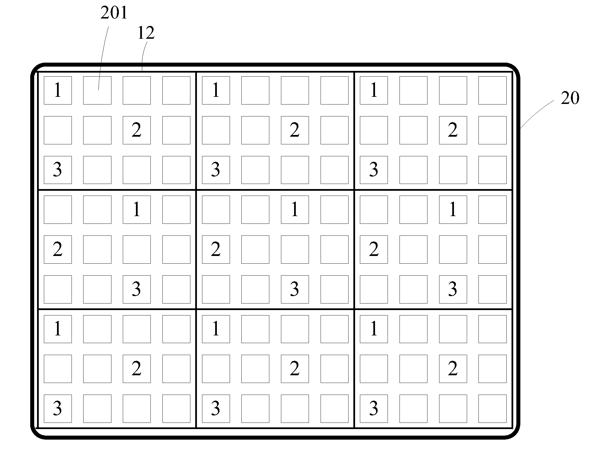
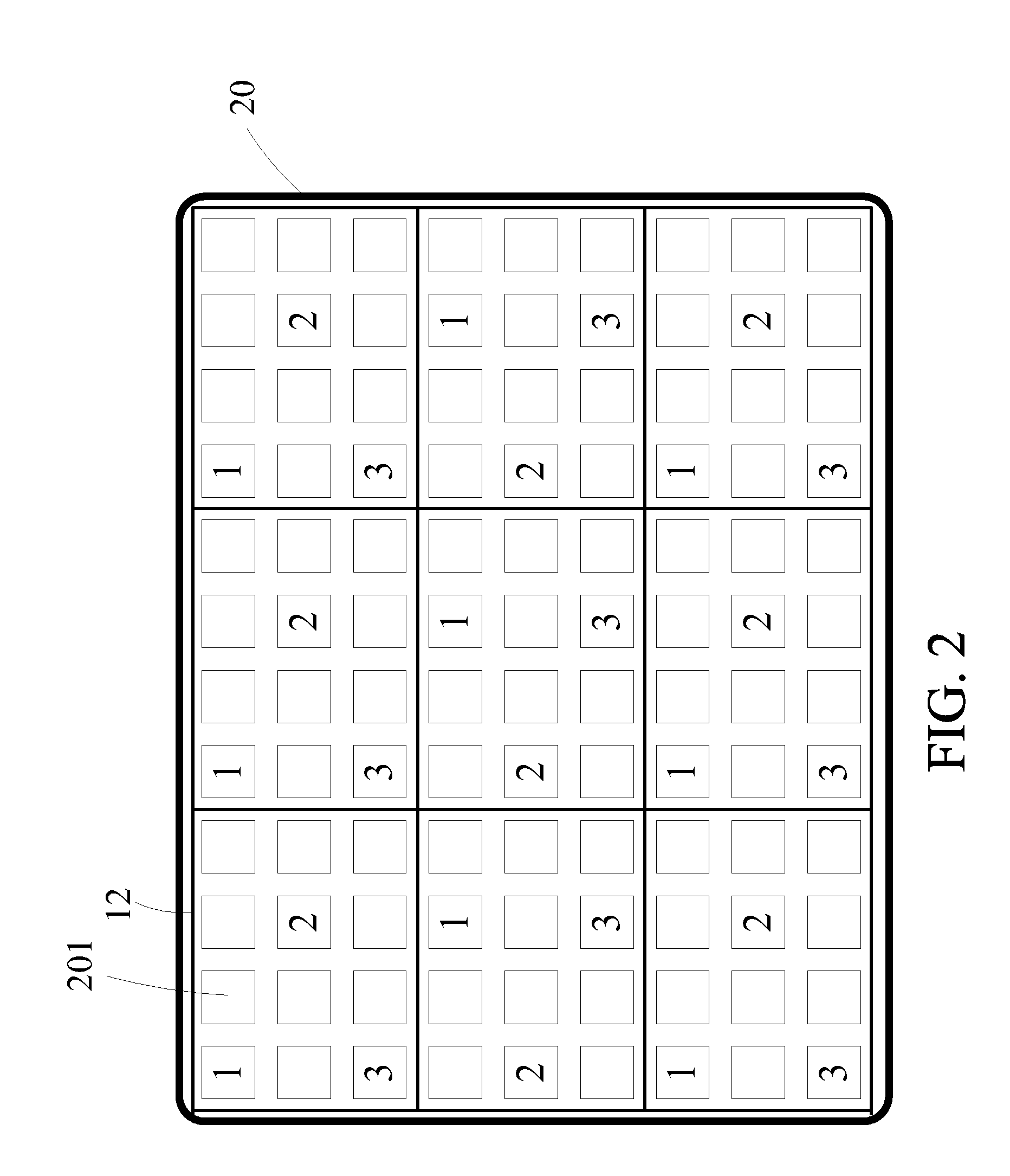
[0026]Please refer to FIG. 3, which illustrates a single one touch region C1 touched by an object on the touch panel 20 according to the present invention. A dashed circle indicates the touch region C1. Initially, first data are sensed from each of the designated points 1 of the blocks 12 in the first stage of the hierarchical sensing method according to the present invention. The sensing time which is required in the first stage of the hierarchical scanning method is only 1 / N, where each block comprises N points, as compared to the sensing time required by the conventional point-by-point sensing method. In the present embodiment, each block 12 comprises twelve points 12, and therefore the sensing time required by the first stage of the hierarchical sensing method is 1 / 12 of the sensing time required by the conventional point-by-point sensing method. It is noted that the first data of each designated point 1 is a sensed value (e.g. capacitance) of said designated point 1. Then, a se...

second embodiment

[0033]After the designated points 2 are scanned and sensed, the first and second stages of the hierarchical sensing method according to the present invention are performed on the designated points 3. Initially, first data are sensed from each of the designated points 3 in the first stage of the hierarchical sensing method according to the present invention as shown in FIG. 11. Not one touch region is found when scanning the designated points 3, that is, not one possible touched point is determined in the first stage of the hierarchical sensing method according to the present invention. However, the second data of the possible touched points 203 in FIG. 10 (i.e. having the counter values of “6”) are sensed for determining whether the possible touched points 203 in FIG. 10 are touched or not in the second stage of sensing the designated points 3. According to the second data, the counter values of the possible touched points 203 which are determined as un-touched points are “0”, while...


PUM


Abstract

A hierarchical sensing method for a touch panel is disclosed. The touch panel has a matrix of points for detecting a touch or touches. The method includes dividing the points into a plurality of blocks; selecting several points in each one of the blocks as designated points; sensing first data from each one of the designated points; determining a set of possible touched points according to the first data sensed from each one of the designated points; sensing second data from the set of possible touched points; and determining if each one of the possible touched points is an actual touched point according to the second data sensed from said one possible touched point. By using the present invention method, a faster sensing speed and a greater sensing accuracy can be achieved.

Description

TECHNICAL FIELD OF THE INVENTION[0001]The present invention relates to a touch sensing technique, more particularly, to a method for sensing a touch or touches on a touch sensitive device.BACKGROUND OF THE INVENTION[0002]Nowadays, touch sensitive devices are widely used in various applications. Among those, a touch screen which comprises a touch panel is very popular.[0003]Sensing speed is very important in the performance of a touch panel. FIG. 1 is a schematic diagram showing a touch panel 10 scanned by a conventional method. The touch panel 10 comprises a matrix of points 101. Each point 101 is used to sense a touch. The structure of the touch panel 10 is widely known in this field. In addition, the structure of the touch panel 10 is not the focus or the main issue of the present invention, and therefore detailed descriptions thereof are omitted herein.[0004]As shown in FIG. 1, a dashed circle 50 indicates a touch region. Shadowed points 105 are the points in respect to the touch...

Claims


Application Information

Patent Timeline
Patent Type & Authority Applications(United States)
IPC IPC(8): G06F3/041
CPCG06F3/0416G06F3/0446G06F3/04166
Inventor HOU, CHEN-YUKUO, CHIN-HUA
Owner SILICON INTEGRATED SYSTEMS
Why Eureka
Try Eureka