
Capacitive touch apparatus

Inactive Publication Date: 2012-06-07
DELTA ELECTRONICS INC
View PDF6 Cites 6 Cited by
  • Summary
  • Abstract
  • Description
  • Claims
  • Application Information

AI Technical Summary

Benefits of technology

[0009]In view of the foregoing subject, an object of the present invention is to provide a capacitive touch apparatus that can improve the sensing speed by the simple circuit design.
[0028]As mentioned above, the capacitive touch apparatus of the present invention is configured with a first selection unit with a multiplexer for switching the connections between the first voltage difference retrieving unit and a plurality of sensing conductive bars of the first touch unit. In addition, the first voltage difference retrieving unit includes a first retrieving device and a second retrieving device for respectively retrieving the voltages of two ends of the voltage-drop device so as to determine the touch position and touch time. Furthermore, the capacitive touch apparatus of the present invention further includes a second touch unit, which is electrically connected with the first touch unit, without increasing complex connections and detecting the touch position. Accordingly, the capacitive touch apparatus of the present invention can improve the sensing speed and reduce the manufacturing cost by the simple circuit design.

Problems solved by technology

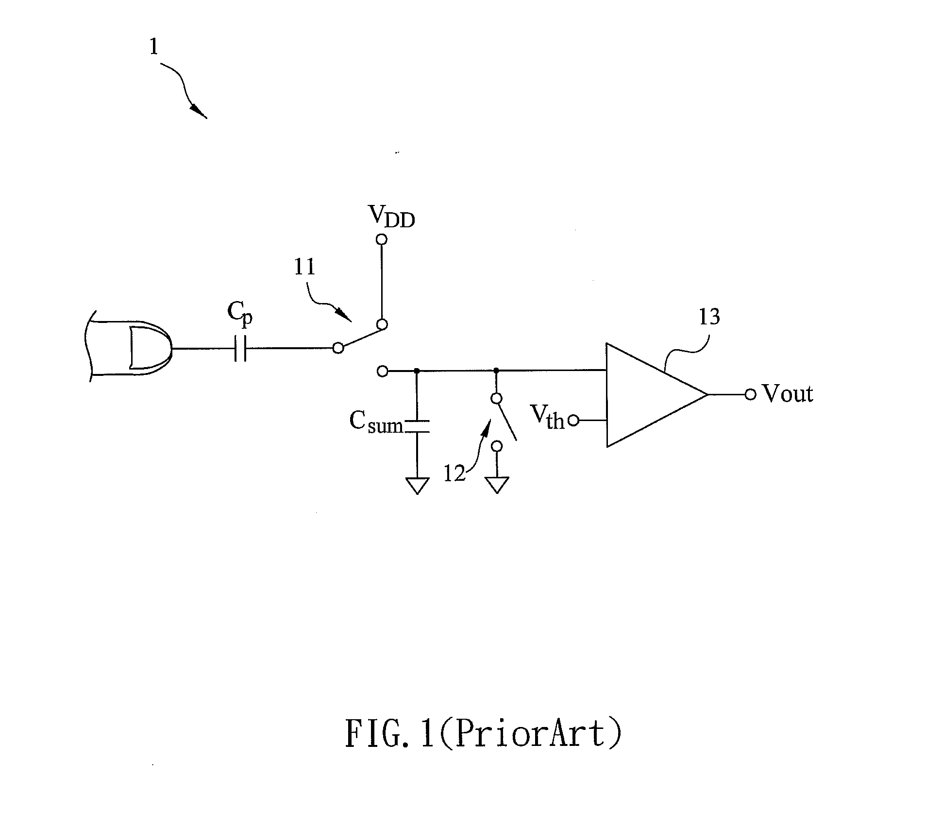
However, because the capacitive touch apparatus 1 needs the charging and discharging procedures of two capacitors for detecting the touch operation, it spends more time in the detecting so that the response time of the capacitive touch apparatus 1 is slower.
In addition, the conventional capacitive touch apparatus usually uses the detecting circuit with single end sensing wire, so it can not obtain the absolute coordinates of the touch position.

Method used


Image

  • Capacitive touch apparatus
  • Capacitive touch apparatus
  • Capacitive touch apparatus

Examples


Embodiment Construction

[0036]The present invention will be apparent from the following detailed description, which proceeds with reference to the accompanying drawings, wherein the same references relate to the same elements.

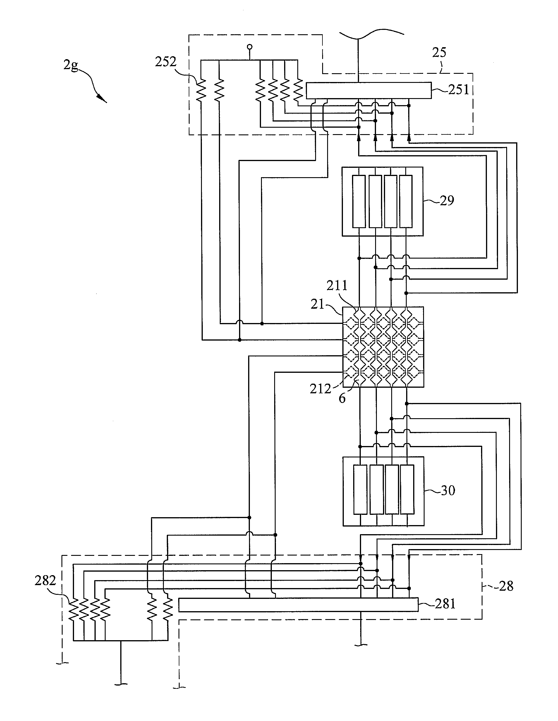
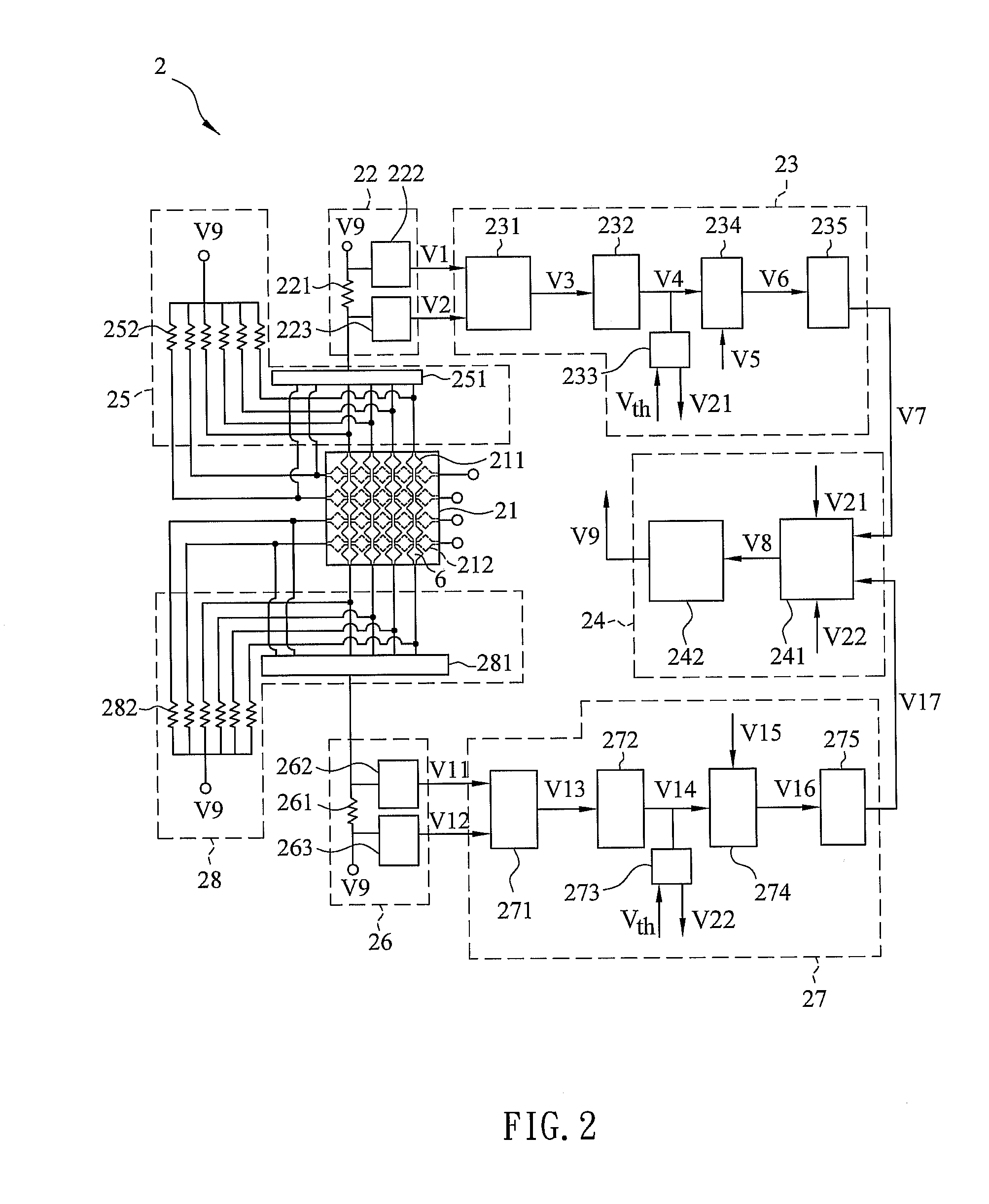
[0037]FIG. 2 is a schematic diagram showing a capacitive touch apparatus 2 according to a preferred embodiment of the present invention. The capacitive touch apparatus 2 includes a first touch unit 21, a first voltage difference retrieving unit 22, a first feedback signal generating unit 23, a control unit 24 and a first selection unit 25.

[0038]The first touch unit 21 includes a touch substrate (not shown) and a first conductive layer 211. The touch substrate can be a substrate of a touch panel, which is made of glass or plastic. The first conductive layer 211 is shown as the solid lines in the figure and includes a plurality of sensing conductive bars. Each of the sensing conductive bars is formed by connecting a plurality of sensing electrodes 6 in series. The sensing electrode 6 of...


PUM


Abstract

A capacitive touch apparatus includes a first touch unit, a first voltage difference retrieving unit, a first feedback signal generating unit, and a control unit. The first touch unit has a touch substrate and a first conductive layer. The first voltage difference retrieving unit is electrically connected with the first conductive layer and outputs a first voltage signal and a second voltage signal. The first feedback signal generating unit outputs a first feedback signal according to the variation of the voltage difference between the first voltage signal and the second voltage signal. The control unit receives the first feedback signal for computing the touch position and outputs a power signal to the first voltage difference retrieving unit. Hence, the capacitive touch apparatus improves the sensing speed and reduces the manufacturing cost by the simple circuit design.

Description

CROSS REFERENCE TO RELATED APPLICATIONS[0001]This Non-provisional application claims priority under 35 U.S.C. §119(a) on Patent Application No(s). 099141663 filed in Taiwan, Republic of China on Dec. 1, 2010, the entire contents of which are hereby incorporated by reference.BACKGROUND OF THE INVENTION[0002]1. Field of Invention[0003]The present invention relates to a touch apparatus and, in particular, to a capacitive touch apparatus.[0004]2. Related Art[0005]The touch panels are easily operated, so they are applied to various kinds of electronic products, such as mobile communication, consumer electronic devices, to replace the traditional buttons. In these electronic products, the display panel and the touch panel, which is used as the input device, are combined, so that the electronic products become more valuable.[0006]FIG. 1 is a schematic diagram showing a conventional capacitive touch apparatus 1, which senses the touch operation by charge transfer. The capacitive touch appar...

Claims


Application Information

Patent Timeline
IPC IPC(8): G06F3/044
CPCG06F3/044G06F3/0416G06F3/04166G06F3/0446
Inventor CHANG, SEANCHANG, CHII-HOWKUO, CHIN-WEI
Owner DELTA ELECTRONICS INC
Learn More