Eureka AIR delivers breakthrough ideas for toughest innovation challenges, trusted by R&D personnel around the world.

Image forming apparatus

a technology of forming apparatus and forming tube, which is applied in the direction of electrographic process apparatus, visual presentation, instruments, etc., can solve the problems of sudden blackout, interruption of power supply or sudden blackout, and long-awaited stable power supply, etc., to reduce power consumption, reduce power consumption, and avoid use in the time zone

Inactive Publication Date: 2013-05-02
SHARP KK
View PDF6 Cites 4 Cited by
  • Summary
  • Abstract
  • Description
  • Claims
  • Application Information

AI Technical Summary

Benefits of technology

The invention is a system that monitors power usage and helps manage power consumption. It uses information from external devices to determine peak power use and curbs the number of jobs during that time to save energy. The system also allows users to execute more jobs during off-peak time zones to balance power use. Additionally, the system can determine if a power restriction time zone is entered during job execution and switch to a different counting method accordingly to further reduce power consumption. Overall, the system helps prevent sudden power blackouts and planned interruptions and achieves energy Tip: The invention is a system that helps manage power consumption by monitoring power usage and curbing execution of jobs during peak power usage time zones. This reduces energy consumption and prevents abrupt power blackouts or planned interruptions. The system uses information from external devices to determine peak power use and can switch to a different counting method if a power restriction time zone is entered during job execution. This system is effective in reducing power consumption and promoting energy conservation.

Problems solved by technology

Therefore, such an apparatus has a problem that if the power supplied from the power source runs short during printing, printing abruptly stops.
Considering electricity supply situations of late, however, the stable power supply that has been long taken for granted (guaranteed) may no longer be realistic.
Interruption of power supply or sudden blackout could occur at any time.
Particularly when the image forming apparatus is shared by a plurality of users, many jobs may be handled at one time and, hence, if many jobs are executed at a time zone when electricity use peaks, the maximum power consumption would be so high as to cause power shortage.
The technique described in '421 Reference cannot avoid such a situation.

Method used


Image

  • Image forming apparatus
  • Image forming apparatus
  • Image forming apparatus

Examples


Embodiment Construction

[0038]In the following description, the same components are denoted by the same reference characters. Their functions and names are also the same. Therefore, detailed description thereof will not be repeated.

[0039][Overall System Configuration]

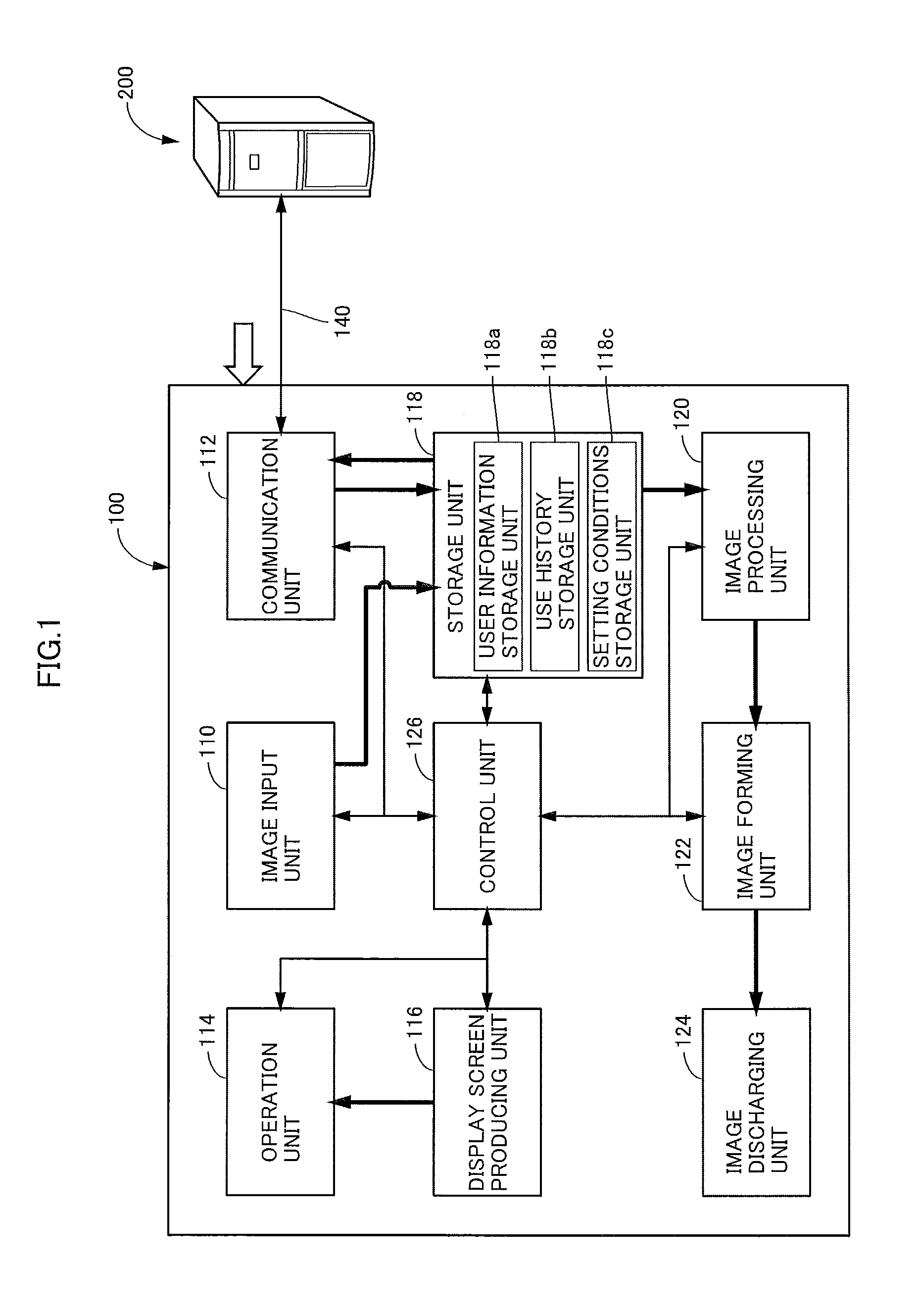
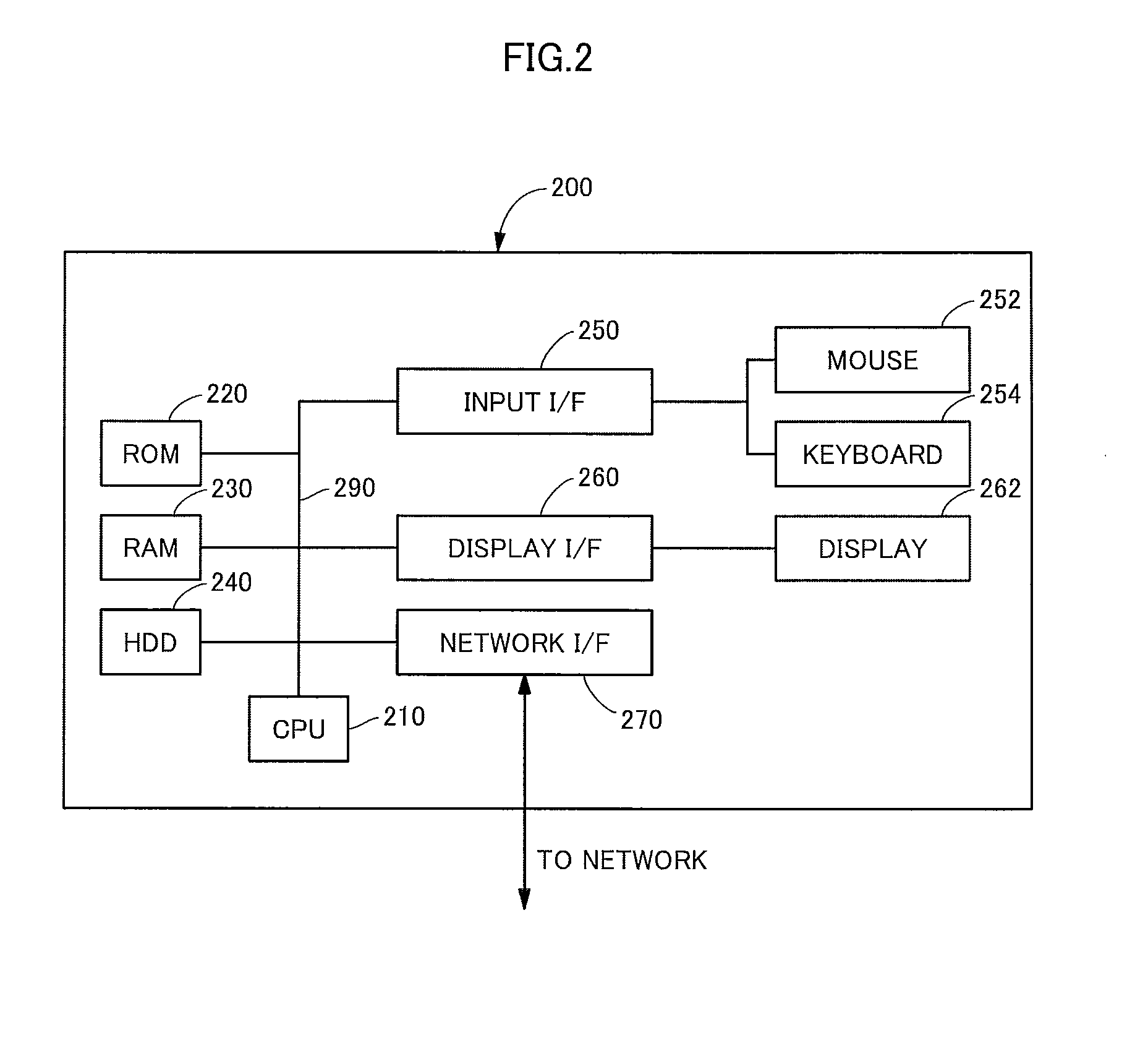
[0040]Referring to FIG. 1, overall system configuration of the network system in accordance with an embodiment of the present invention will be described. The network system includes an image forming apparatus 100 implemented as an MFP, and a server computer 200 holding information related to the state of power supply and transmitting, in response to a request from the image forming apparatus 100, the information related to the state of power supply at the time of request to image forming apparatus 100. Image forming apparatus 100 and server computer 200 are connected to be communicable with each other by a network line 140.

[0041]Image forming apparatus 100 in accordance with the present embodiment has a function of counting the number of outp...


PUM


Abstract

Image forming apparatus communicates with a server computer and obtains information related to state of power supply from the server computer. Based on the obtained information, the image forming apparatus determines whether or not it is in a time zone of peak power consumption. If it is determined to be the time zone of peak power consumption, a method of counting the number of outputs is switched to a weighted counting method, for counting with weight added to the normal counting method.

Description

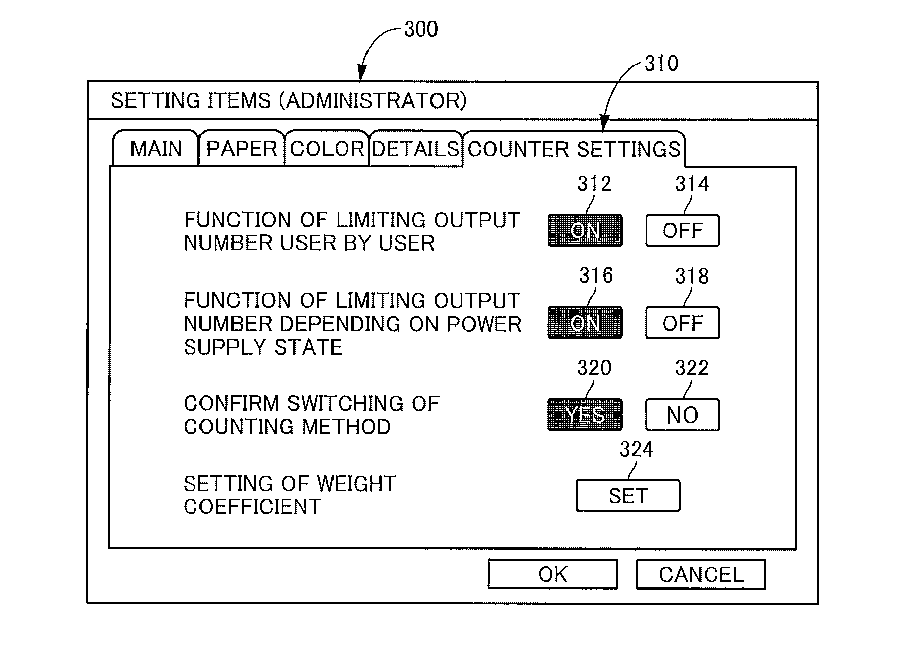
CROSS-REFERENCE TO RELATED APPLICATIONS[0001]This nonprovisional application claims priority under 35 U.S.C. §119(a) on Patent Application No. 2011-235874 filed in Japan on Oct. 27, 2011, the entire contents of which are hereby incorporated by reference.BACKGROUND OF THE INVENTION[0002]1. Field of the Invention[0003]The present invention relates to an image forming apparatus connectable to a network.[0004]2. Description of the Background Art[0005]A portable, handy image forming apparatus has been known as an image forming apparatus enabling on-site printing of image data saved in a portable terminal such as a note type PC, a digital still camera and the like. Japanese Patent Laying-Open No. 2002-205421 (hereinafter referred to as '421 Reference) discloses such a portable image forming apparatus (print control device). A portable image forming apparatus generally uses a battery as a power source. Therefore, such an apparatus has a problem that if the power supplied from the power sou...

Claims


Application Information

Patent Timeline
IPC IPC(8): G06K15/00
CPCG03G15/5004G03G2215/00109H04N1/00244H04N1/00344H04N1/00411H04N1/00424H04N1/00432H04N1/00472H04N1/00474H04N1/00477H04N1/00482H04N1/00832H04N1/00888H04N1/2338H04N1/2346H04N1/346H04N1/348H04N1/4413H04N1/4433H04N2201/0039H04N2201/0094H04N2201/3202H04N2201/0082H04N2201/3205G03G15/502G03G15/5083
Inventor KODAMA, HIROTAKA
Owner SHARP KK
Why Eureka
Eureka Blog
Learn More