Methods and Devices for Object Detection

a technology of object detection and method, applied in the field of video surveillance applications, can solve the problems of large computational cost of descriptors, limited amount of extracted information, and difficulty in automating feature analysis and detection, and achieve the effect of low complexity

Inactive Publication Date: 2015-08-13
SIEMENS CORP
View PDF4 Cites 2 Cited by
  • Summary
  • Abstract
  • Description
  • Claims
  • Application Information

AI Technical Summary

Benefits of technology

[0010]The device shows the advantage that the execution is simple but robust compared to prior art algorithms. For example, the generation of the respective components allows a fast execution of non-specialized hardware (e.g., a personal computer). In addition, the way the component is generated sets small pixel intensity differences, such as luminance differences, of a pair of pixels to zero and big differences to one. If the biggest pixel intensity differences are between the pixels from the object and pixels from the background, the presented device sets between samples with the same class (e.g., object—object, background—background) to zero and test between samples from different classes to one (e.g., object-background). In addition the device is less sensitive to background clutter and noise.
[0013]This setting of the feature descriptor results in a binary coded feature descriptor that shows the advantages that the feature descriptor may be coded very tight, and a comparison with reference feature vectors are accomplished with low complexity.
[0019]This setting of the feature descriptor results in a binary coded feature descriptor that shows the advantages that the feature descriptor may be coded very tight, and a comparison with reference feature vectors are to be accomplished with low complexity.

Problems solved by technology

In order to automate data processing of surveillance images, automatic feature analysis and detection are major challenges.
However, these descriptors may be computationally expensive to compute.
This comes at the cost that the amount of extracted information is very limited.

Method used


Image

  • Methods and Devices for Object Detection
  • Methods and Devices for Object Detection
  • Methods and Devices for Object Detection

Examples


Embodiment Construction

[0025]Elements in the figures with the same function are shown by the same element number.

[0026]In a first example, an embodiment is described in the area of a manufacturing line. The manufacturing line produces tools made of metal, such as a saw. In order to provide the manufacturing quality of the production line, each manufactured tool is to be inspected visually in order to detect production errors and to be able to discard tools that show, for example, production errors.

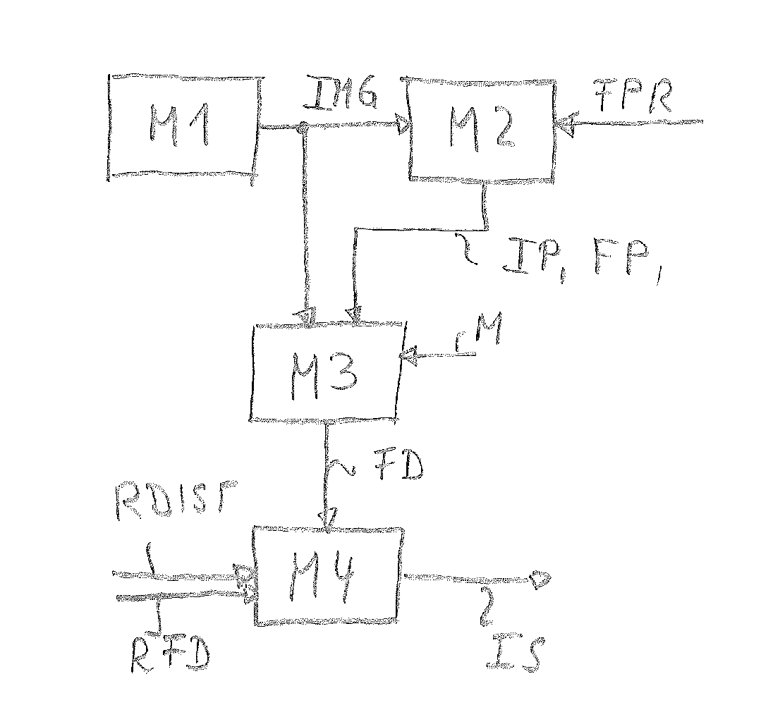
[0027]In a first act, a first module M1 (e.g., a high resolution camera) generates one image of the tool. The image may consist of 2000×1000 pixels, where each pixel shows a luminance resolution of 16 bit.

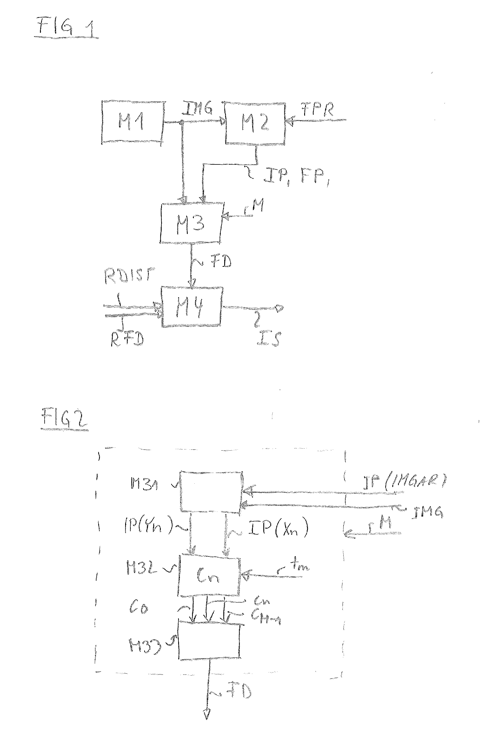
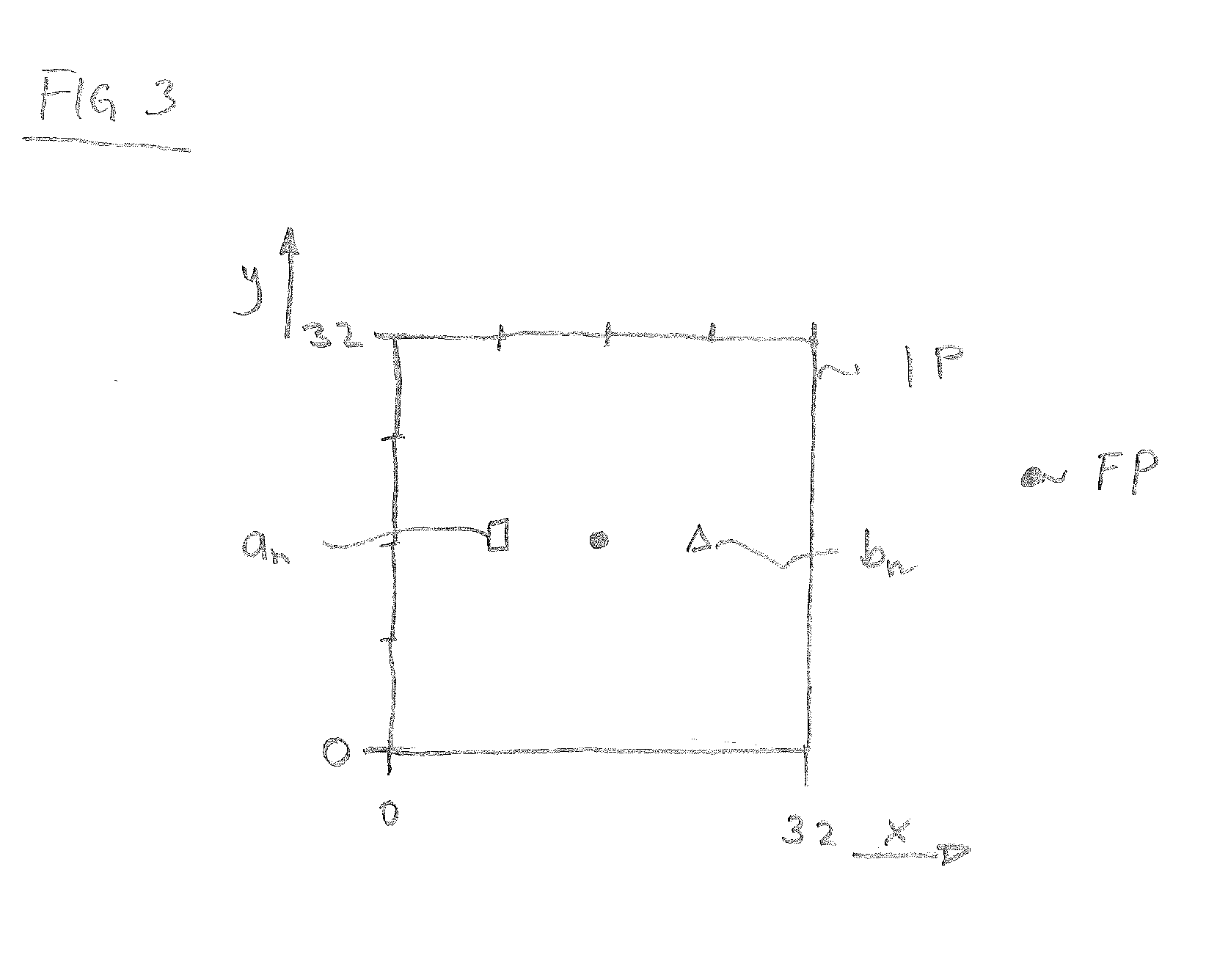
[0028]In a second act, a second module M2 determines at least one feature point FP. The feature point FP may define a location of an image patch IP that is used for determining a feature descriptor FD. The image patch IP defines an image area IMGAR (e.g., 32×32 pixels) that is located inside the image IMG. The ...


PUM


Abstract

Object detection includes providing an image and determining at least one feature point. The at least one feature point defines a location of an image patch used for determining a feature descriptor, and the image patch defines an image area of the image. The feature descriptor is generated based on respective image intensities of a number of respective pairs of pixels with two dimensional coordinates located inside the image patch. An n-th component of the feature descriptor for an n-th pair of pixels is derived. A threshold is set depending on the number. The feature descriptor is generated by an arrangement of the M components. An indication signal is generated for a detected object when the feature descriptor is within a predefined distance to a reference feature descriptor.

Description

BACKGROUND[0001]The present embodiments relate to methods and devices for object detection.[0002]In recent years, video surveillance applications become more and more popular. Security is enhanced in many areas such as in underground trains or on buses, and automated processes use surveillance technology (e.g., for quality assessment or for controlling processes such as traffic light control).[0003]In order to automate data processing of surveillance images, automatic feature analysis and detection are major challenges. For example, a feature descriptor of a feature analysis and detection system is a representation of features extracted over an image area (e.g., image patch). For the purpose of finding an image patch within a large image (e.g., detection), the representation of the extracted information is to be dissimilar for dissimilar patches and similar for similar patches. The representation may be invariant to certain transformations of the extracted features. The type of inva...

Claims


Application Information

Patent Timeline
Patent Type & Authority Applications(United States)
IPC IPC(8): G06K9/00G06K9/62G06K9/46
CPCG06K9/00624G06K9/6202G06K9/4604G06V10/462
Inventor AMON, PETERERNST, JANHUTTER, ANDREASREHM, JOHANNESSINGH, VIVEK KUMAR
Owner SIEMENS CORP
Why Eureka
Try Eureka