Method and apparatus for beam selection for a multibeam satellite communications system

a satellite communications system and beam selection technology, applied in the field of multibeam satellite communications systems, can solve the problem that the processing of spot beams used by vsats may not be automated

Active Publication Date: 2013-05-02
HUGHES NETWORK SYST
View PDF1 Cites 17 Cited by
  • Summary
  • Abstract
  • Description
  • Claims
  • Application Information

AI Technical Summary

Problems solved by technology

The process a VSAT uses to find a spot beam may not be automated, and may be complex.

Method used


Image

  • Method and apparatus for beam selection for a multibeam satellite communications system
  • Method and apparatus for beam selection for a multibeam satellite communications system
  • Method and apparatus for beam selection for a multibeam satellite communications system

Examples


Embodiment Construction

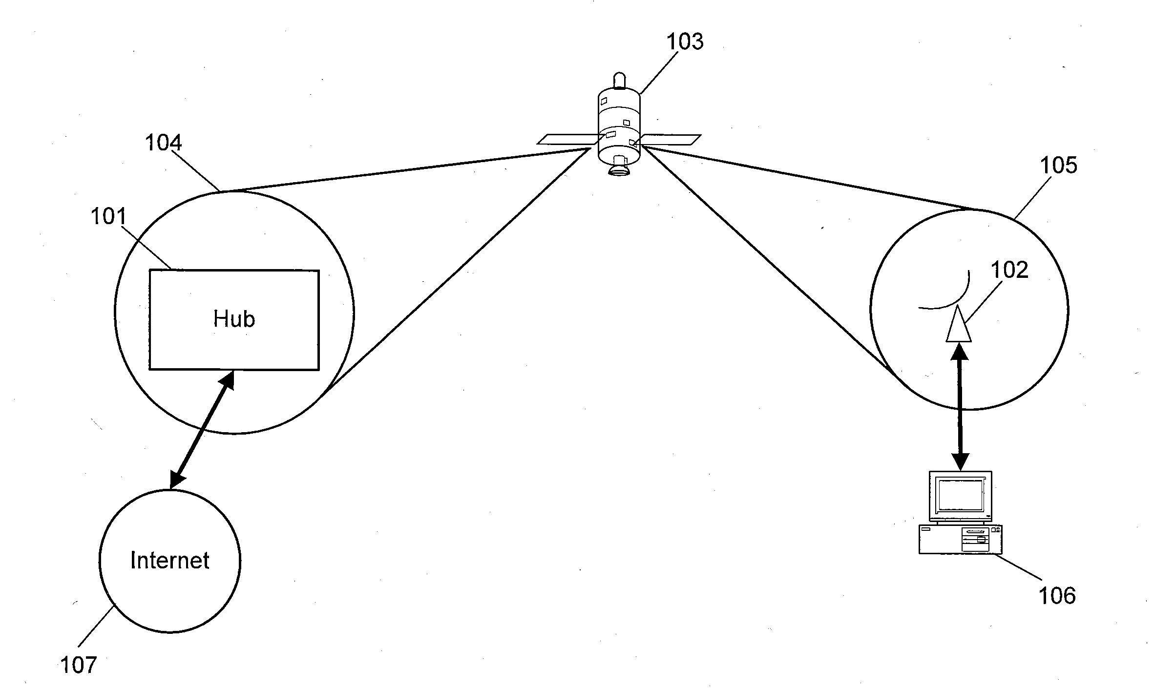
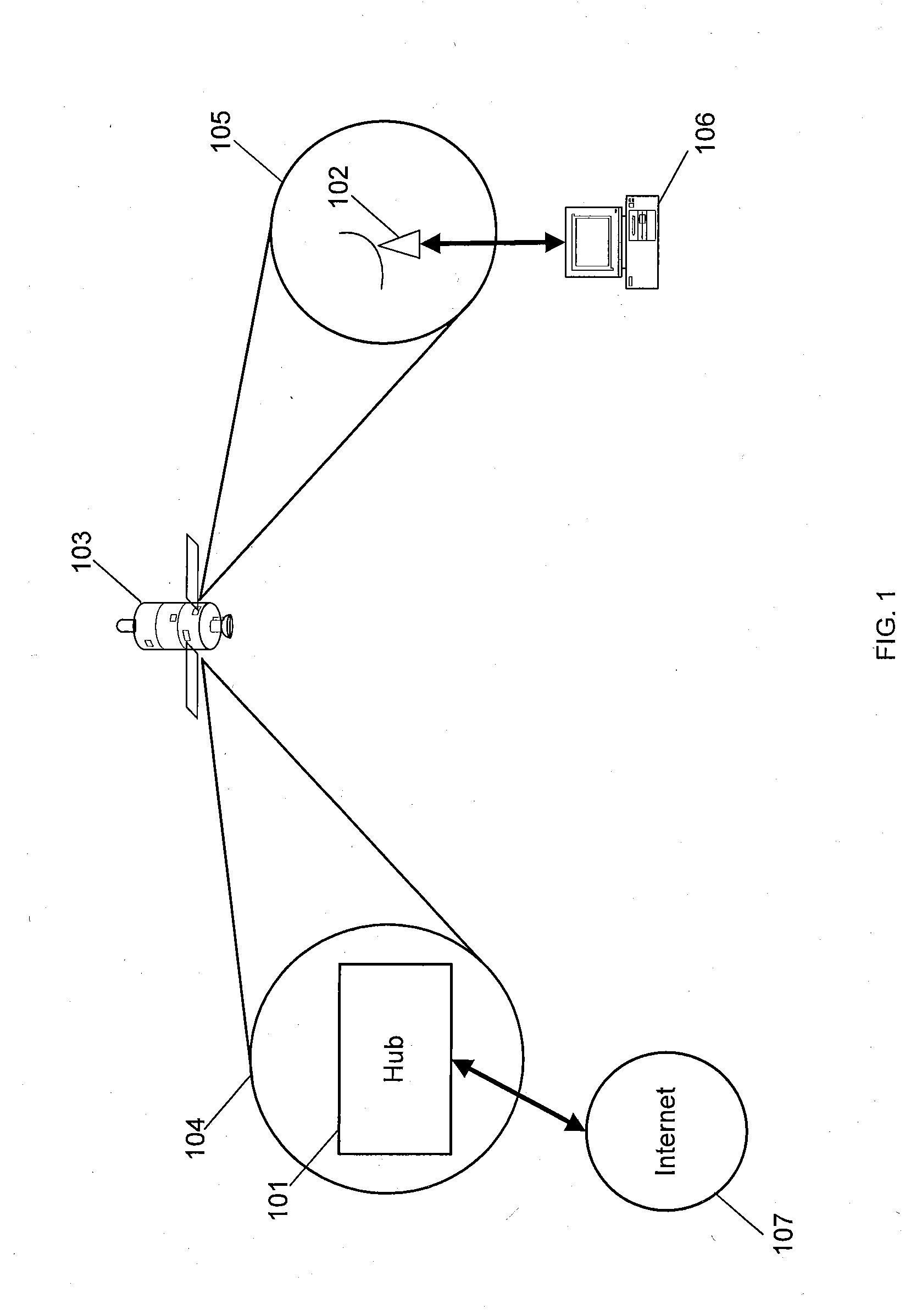
[0013]FIG. 1 depicts an exemplary satellite communications system. The satellite communications systems may include a hub (gateway, or satellite ground station) 101, a Very Small Aperture Terminal (VSAT) 102, a satellite 103, a gateway spot beam 104, a user spot beam 105, a remote host 106, and the Internet 107,

[0014]The hub 101 may be a satellite ground station, hub or gateway for a satellite communications system, and may be connected to the VSAT 102 through the satellite 103. Feeder links through the gateway spot beam 104 may carry data between the hub 101 and the satellite 103, and may include a forward uplink for transmitting data from the hub 101 to the satellite 103, and a return downlink for transmitting data from the satellite 103 to the hub 101. The hub 101 may be a high capacity, large antenna earth station with connectivity to ground telecommunications infrastructure, such as, for example, the Internet 107.

[0015]The VSAT 102 may be used by end users to access the satelli...


PUM


Abstract

An apparatus for beam selection for a multibeam satellite communications system including a VSAT with a remote satellite dish for sending and receiving RF signals and processor for calculating a normalized distance metric for user spot beams, selecting the user spot beam with the lowest normalized distance metric, and finding an outroute on the selected user spot beam using the remote satellite dish.

Description

BACKGROUND[0001]In a multibeam satellite communications system, each Very Small Aperture Terminal (VSAT) may need to be told, or may otherwise figure out, which of several available satellite spot beams the VSAT should use to establish connectivity to the satellite communications system. VSATs may be assigned to spot beams based on their geographic position. If a VSAT's location, when plotted on a map, lies within a particular contour of a spot beam, the VSAT may be assigned to that spot beam. In mobile satellite systems such as the THURAYA system, spot beam selection has been based on a VSAT's measurement of signal strength in nearby spot beams, as the VSAT attempts to find the “best” spot beam. The process a VSAT uses to find a spot beam may not be automated, and may be complex.BRIEF SUMMARY[0002]It is an object of the present invention to provide a method and apparatus for beam selection for a multibeam satellite communications system.[0003]In accordance with an aspect of the pre...

Claims


Application Information

Patent Timeline
Patent Type & Authority Applications(United States)
IPC IPC(8): H04W92/00
CPCH04B7/2041H04B7/18528
Inventor ROOS, DAVELEON, GIADIRA
Owner HUGHES NETWORK SYST
Why Eureka
Try Eureka