Integration of computerized project planning and project diagramming

a project planning and project diagramming technology, applied in computing, instruments, data processing applications, etc., can solve the problems of inability to detect or correct increase the amount of labor required, and inadvertent creation of deviations between the architecture diagram and the product management plan

Inactive Publication Date: 2013-05-02
IBM CORP
View PDF6 Cites 6 Cited by
  • Summary
  • Abstract
  • Description
  • Claims
  • Application Information

AI Technical Summary

Problems solved by technology

Even through the project plan and the architectural diagram share much common information, the plan and diagram must nevertheless be created independently, greatly increasing the amount of labor required.
Similarly, deviations between the architecture diagram and the product management plan may be inadvertently created through mishandled updates, errors, omissions and revisions.
There is no easy to way to detect or correct the deviations outside of tedious manual examination of the diagram and the plan.
Finally, the accessibility of information on the plan and diagram is hampered by the lack of mutual communication.

Method used


Image

  • Integration of computerized project planning and project diagramming
  • Integration of computerized project planning and project diagramming
  • Integration of computerized project planning and project diagramming

Examples


Embodiment Construction

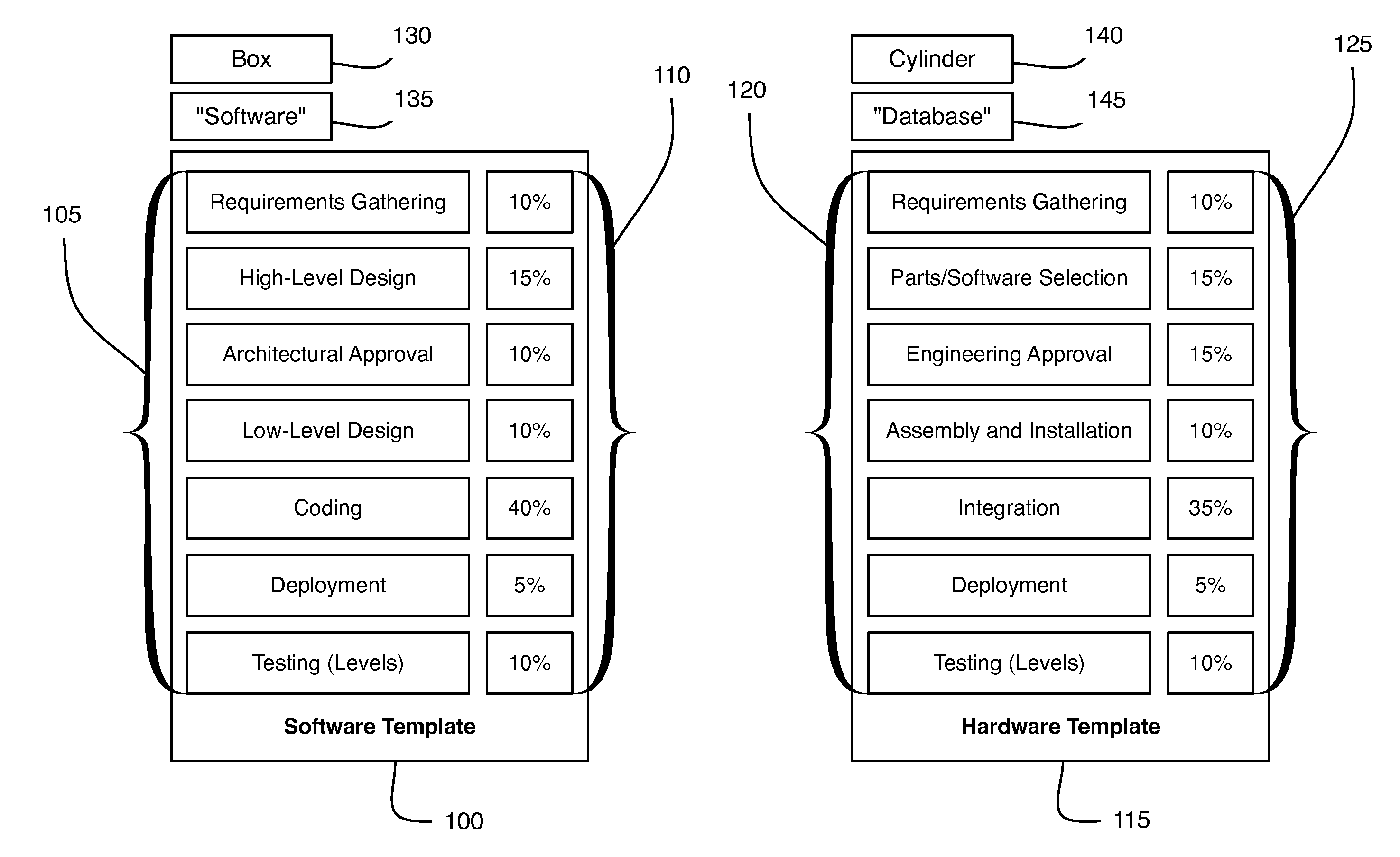
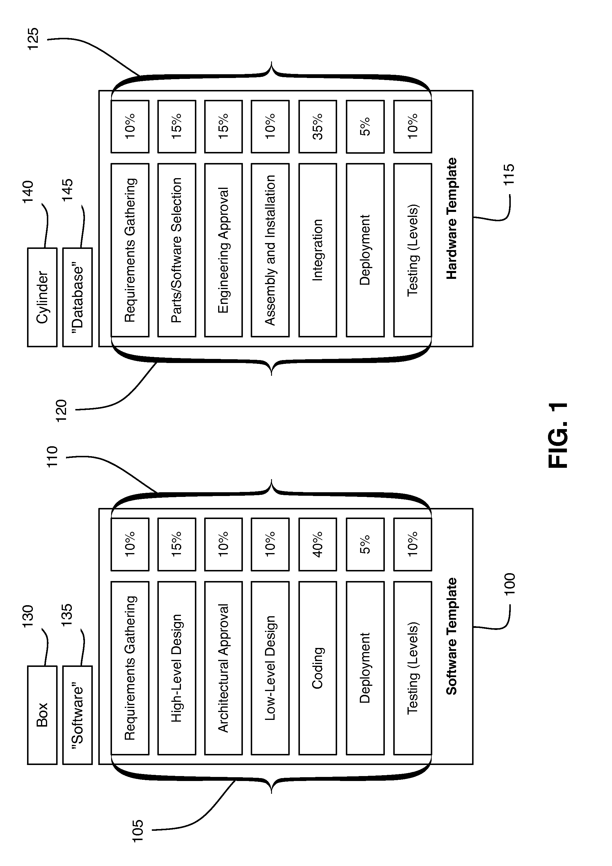
[0021]This application discloses a computer-implemented integrator that integrates project planning software and diagramming software. The integrator functions by capitalizing on a consistent format of entities and concepts on a project architecture diagram. Architectural diagrams may implement a consistent format of recognizable, predefined shapes, labels and other identifiers to represent project entities. For example, a hardware system project entity, such as a database, may be represented consistently with a cylinder, and labeled consistently as a “database.” The integrator disclosed herein may utilize the cylinder shape or “database” label as one or more identifiers, enabling the integrator to automatically detect the type of entity that is represented based on the identifier, retrieve a predefined template associated with the identifier, and translate the entity into a corresponding entity.

[0022]Pre-defined templates may each correspond to different types of project components...


PUM


Abstract

A computer implemented system and method for integrating project architecture diagramming with project planning is disclosed. A project template is stored in a database, the project template comprising at least two component tasks. The project template is associated with an architecture entity identifier. A project architecture diagram is received comprising at least one diagram entity, each diagram entity being associated with at least one diagram entity identifier. The diagram entity identifier is compared to the architecture entity identifier to identify the project template as the project template associated with the diagram entity. A project component is generated from the identified project template, the project component corresponding to the diagram entity and populated with the component tasks from the identified project template. A project work plan is populated with the project component.

Description

BACKGROUND[0001]1. Field[0002]This disclosure relates generally to computerized project management, and, more specifically, to a computer-implemented system and method for integrating computerized diagramming software and computerized project management software.[0003]2. Background[0004]The execution of complex projects are typically supported by project management software and diagramming software. Project management software is traditionally used to create project plans that enable project execution by coordinating time allocation, budget estimation, personnel deployment, communication, scheduling, product deployment and product testing. Diagramming software is used to produce graphic architectural diagrams illustrating project concepts such as software and / or hardware entities, data flows and system dependencies. Naturally, certain project entities may be represented on both the project plan and the architectural diagram.[0005]Even through the project plan and the architectural d...

Claims


Application Information

Patent Timeline
Patent Type & Authority Applications(United States)
IPC IPC(8): G06Q10/06
CPCG06Q10/06
Inventor BOSTICK, JAMES E.GANCI, JR., JOHN M.KAEMMERER, JOHN P.TRIM, CRAIG M.
Owner IBM CORP
Why Eureka
Try Eureka