Converging illuminant device

a technology of illuminant and illuminant axis, which is applied in the direction of semiconductor devices, lighting and heating apparatus, instruments, etc., can solve the problems of low illuminant efficiency and central luminous intensity, large reflection angle of light emitted by the flat illuminant, and large illuminant efficiency. , to achieve the effect of excellent light converging

Active Publication Date: 2013-05-09
AUTOMOTIVE RES & TESTING CENT
View PDF9 Cites 13 Cited by
  • Summary
  • Abstract
  • Description
  • Claims
  • Application Information

AI Technical Summary

Benefits of technology

[0008]The main objective of the invention is to provide a converging illuminant device having an excellent light converging effect.

Problems solved by technology

However, angles of reflection of light emitted by the flat illuminant are large and the light emitted by the flat illuminant disperses.
Consequently, illuminant efficiency and central luminous intensity are low.
Nevertheless, a light converging effect provided by the enhancement film is still insufficient and needs improvement.

Method used


Image

  • Converging illuminant device
  • Converging illuminant device
  • Converging illuminant device

Examples


Embodiment Construction

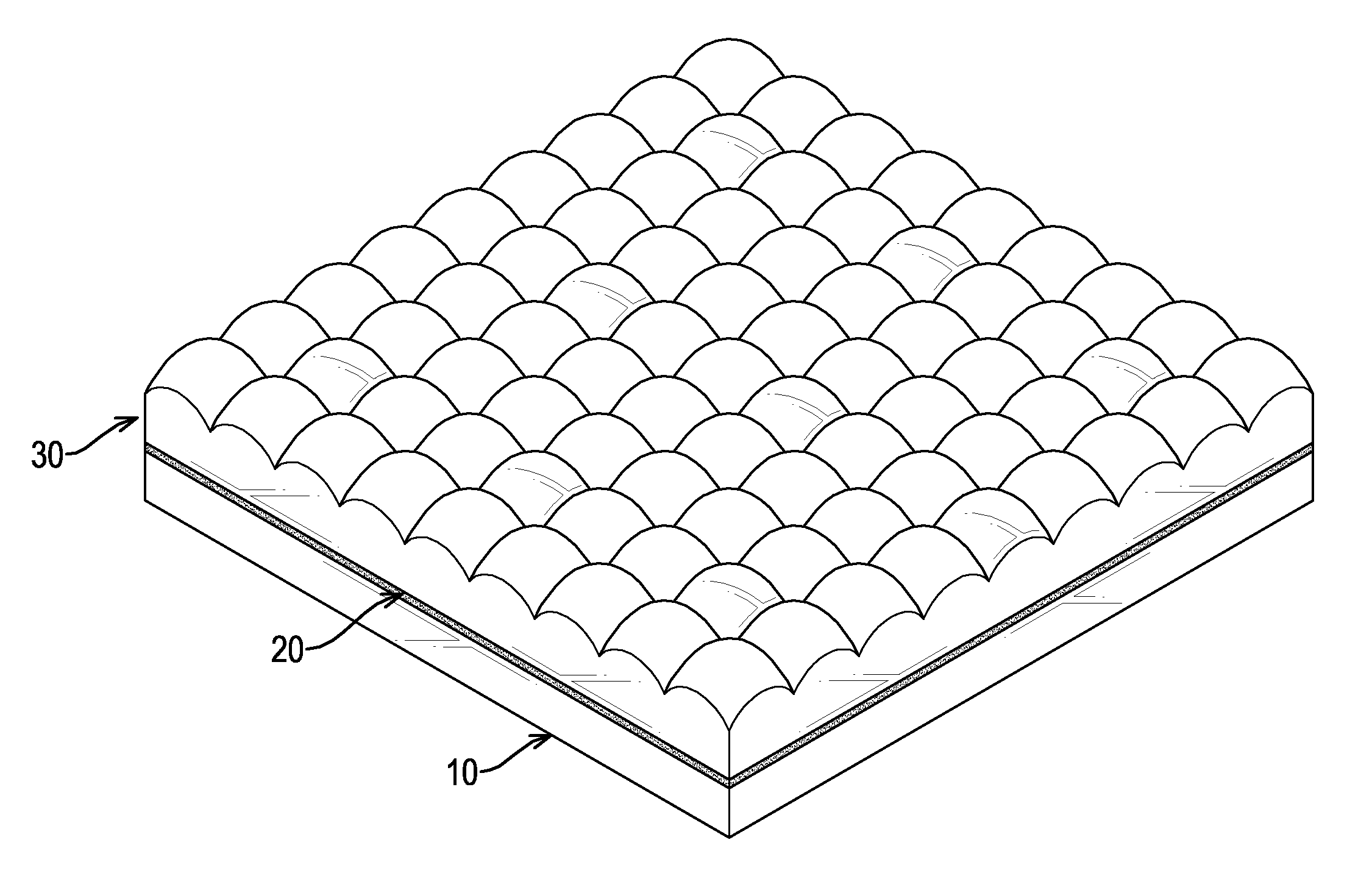
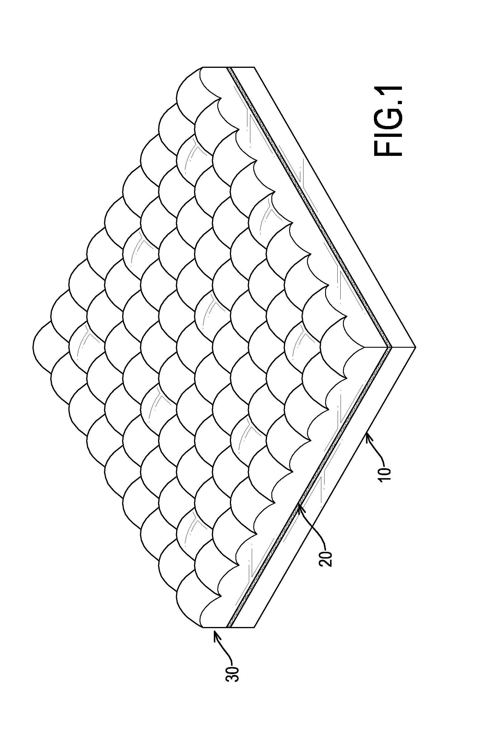
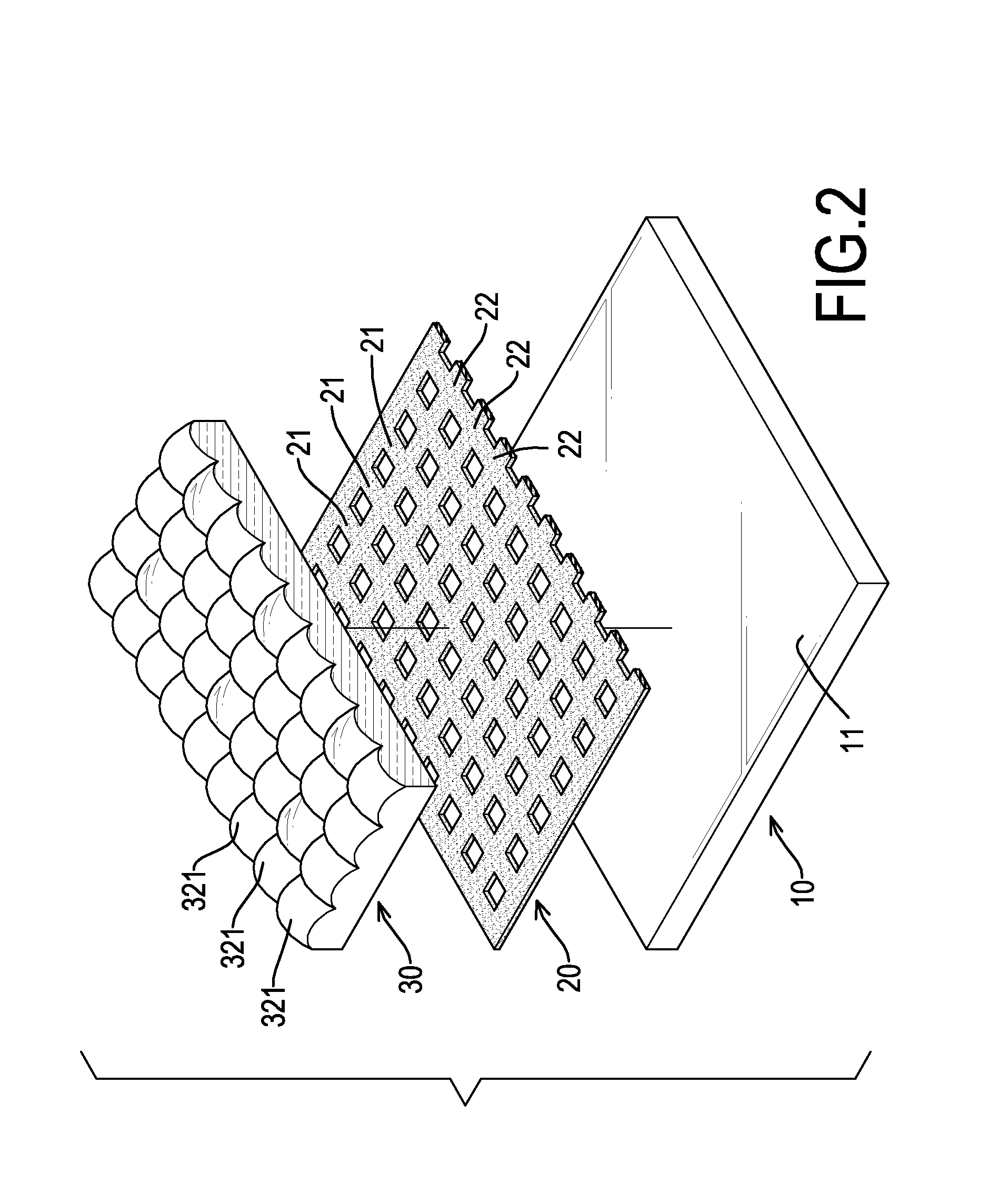
[0019]With reference to FIGS. 1 to 3, a converging illuminant device in accordance with the present invention in turn comprises a flat illuminant 10, a reflective layer 20 and an enhancement film 30.

[0020]The flat illuminant 10 is a flexible sheet and has an illuminant surface 11 and a reflective surface 12 opposite to the illuminant surface 11. Preferably, the illuminant 10 comprises multiple OLEDs (Organic Light Emitting Diodes).

[0021]The reflective layer 20 abuts the illuminant surface 11, is grille-shaped and has multiple longitudinal strips 21 and multiple lateral strips 22. The longitudinal strips 21 are parallel to each other. The lateral strips 22 are parallel to each other.

[0022]Preferably, each longitudinal strip 21 is perpendicular to each lateral strip 22. A width of each longitudinal strip 21 is the same as that of each lateral strip 22.

[0023]With reference to FIGS. 2 to 4, the enhancement film 30 is pervious to light, is securely connected with the reflective layer 20 ...


PUM


Abstract

A converging illuminant device has a flat illuminant, a reflective layer and an enhancement film. The reflective layer abuts the flat illuminant, is grille-shaped and has multiple longitudinal strips and multiple lateral strips. The enhancement film is securely connected with the reflective layer and has an emissive surface. The emissive surface has multiple free-form curved areas, multiple longitudinal lines and multiple lateral lines. The longitudinal lines respectively align with the longitudinal strips. The lateral lines respectively align with the lateral strips. Because the reflective layer is grille-shaped, light definitely passes through central positions of the free-form curved areas, angles of refraction of the light are small and the light can be effectively converged. Consequently, illuminant efficiency and central luminous intensity are increased.

Description

BACKGROUND OF THE INVENTION[0001]1. Field of the Invention[0002]The present invention relates to a converging illuminant device, and more particularly to a converging illuminant device having an excellent light converging effect.[0003]2. Description of Related Art[0004]A conventional flat illuminant comprises multiple OLEDs (Organic Light Emitting Diode) and shows a Lambertian pattern of light. However, angles of reflection of light emitted by the flat illuminant are large and the light emitted by the flat illuminant disperses. Consequently, illuminant efficiency and central luminous intensity are low.[0005]When the conventional flat illuminant is applied to a rear lamp, large number of OLEDs are necessary to be arranged to a specific pattern and to achieve a statutory luminous intensity in compliance with laws, such as regulations about rear lamps mounted on a back of a car.[0006]An enhancement film is often attached to a top surface of the flat illuminant to condense and shape lig...

Claims


Application Information

Patent Timeline
Patent Type & Authority Applications(United States)
IPC IPC(8): F21V7/04
CPCF21S6/002F21V5/007F21Y2105/008F21V7/0016F21V11/14F21V5/02F21Y2105/00F21Y2115/15F21S43/145
Inventor HO, YAO-MINHSU, JIH-TAO
Owner AUTOMOTIVE RES & TESTING CENT
Why Eureka
Try Eureka