
Method and apparatus for transmitting and receiving downlink control information in a mobile communication system supporting uplink packet data service

a mobile communication system and control information technology, applied in the field of cdma communication systems, can solve the problems of interference of uplink signals with one another, and reducing reception performance in node b, so as to reduce downlink signaling overhead

Active Publication Date: 2013-05-09
SAMSUNG ELECTRONICS CO LTD
View PDF2 Cites 9 Cited by
  • Summary
  • Abstract
  • Description
  • Claims
  • Application Information

AI Technical Summary

Benefits of technology

The present invention aims to reduce the signaling overhead and improve the efficiency of transmission in a mobile communication system where a Node B controls the uplink data rate of a UE. This is achieved by providing a method and apparatus for interpreting the scheduling grant transmitted by the Node B and reducing the downlink signaling overhead arising from transmitting the scheduling grant. These improvements can lead to faster data transmission and lower latency, improving the overall performance of the mobile communication system.

Problems solved by technology

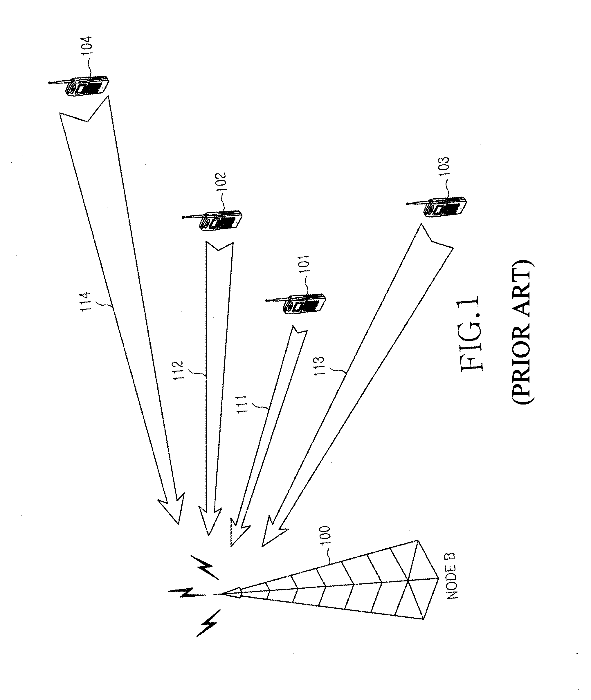
Due to asynchronization between uplink signals from different UEs, the uplink signals interfere with one another.
As the Node B receives more uplink signals, an uplink signal from a particular UE suffers from increased interference, thereby decreasing reception performance in the Node B. This problem can be overcome by increasing the uplink transmit power of the UE, but the increased transmit power in turn serves as interference to other uplink signals.
Thus, the reception performance is still decreased in the Node B. The total power of uplink signals that the Node B can receive with reception performance at or above an acceptable level is limited.

Method used


Image

  • Method and apparatus for transmitting and receiving downlink control information in a mobile communication system supporting uplink packet data service
  • Method and apparatus for transmitting and receiving downlink control information in a mobile communication system supporting uplink packet data service
  • Method and apparatus for transmitting and receiving downlink control information in a mobile communication system supporting uplink packet data service

Examples


embodiment 1

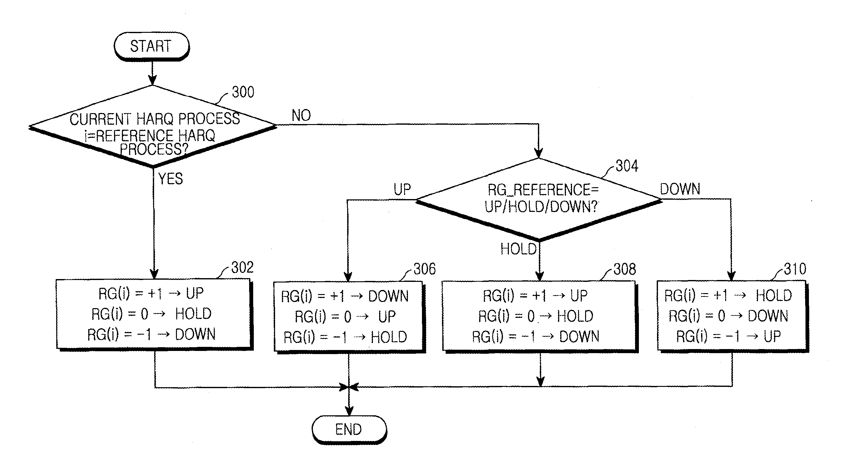
[0050]FIG. 3 is a flowchart illustrating an operation for generating and interpreting a scheduling grant according to an exemplary embodiment of the present invention.

[0051]Referring to FIG. 3, the Node B determines whether an HARQ process for which to allocate a data rate is a reference HARQ process in step 300. The HARQ process for which to allocate a data rate is an HARQ process to be allocated to a current TTI and it is referred to as “a current HARQ process”. If the current HARQ process is a reference HARQ process, the Node B sets an RG to +1 for a rate increase, 0 (that is, DTX) for no rate change, or −1 for a rate decrease for the reference HARQ process according to scheduling in the Node B scheduler in step 302. Since the RG received from the Node B is intended for the reference HARQ process, the UE interprets an RG of +1 as a rate increase, an RG of 0 as no rate change, and an RG of −1 as a rate decrease.

[0052]On the other hand, if the current HARQ process is a non-referenc...

embodiment 2

[0080]FIG. 6 is a flowchart illustrating an exemplary operation for generating and interpreting a scheduling grant according to an embodiment of the present invention.

[0081]Typically, an up / hold / down command indicated by an RG applied to the same HARQ process number. For instance, if the Node B signals an RG indicating up for HARQ process #2, the UE is supposed to increase an allowed maximum data rate applied to the latest HARQ process #2 by a predetermined level.

[0082]Referring to FIG. 6, the Node B determines whether a current HARQ process to which a data rate is to be allocated is a reference HARQ process in step 600. In the case of a reference HARQ process, the Node B determines up / hold / down for the reference HARQ process with respect to the allowed maximum data rate of the latest HARQ process in step 602. On the other hand, in the case of a non-reference HARQ process, the Node B determines up / hold / down for the non-reference HARQ process with respect to the allowed maximum data ...

embodiment 3

[0084]FIG. 7 is a flowchart illustrating an operation for generating and interpreting a scheduling grant according to another exemplary embodiment of the present invention.

[0085]Referring to FIG. 7, the Node B determines whether a current HARQ process for which to allocate a data rate is a reference HARQ process in step 700. If the current HARQ process is a reference one, the Node B determines an RG value of up / hold / down with respect to the latest allowed maximum data rate of the reference HARQ process for the UE in step 702. On the other hand, if the current HARQ process is a non-reference one in step 700, the Node B determines whether the latest RG of the reference HARQ process indicates up / hold / down in step 704.

[0086]If the RG_reference indicates up, the Node B compares the allowed maximum data rate of the non-HARQ process with the latest allowed maximum data rate of the reference HARQ process in step 706. For a rate increase from the latest allowed maximum data rate of the refer...


PUM


Abstract

A method and apparatus for transmitting and receiving downlink control information in a mobile communication system supporting an uplink packet data service are provided. To transmit packet data in an HARQ mobile communication system, a second transceiver receives an RG as rate control information from a first transceiver. The second transceiver sets the allowed maximum data rate of an HARQ process to which the RG is applied to the allowed maximum data rate of an HARQ process previous to the HARQ process, if the RG indicates hold. The second transceiver transmits packet data within the set allowed maximum data rate to the first transceiver.

Description

PRIORITY[0001]This application is a continuation of U.S. patent application Ser. No. 13 / 281,061, filed Oct. 25, 2011, which is a continuation of U.S. patent application Ser. No. 11 / 272,823, filed Nov. 15, 2005, now issued as U.S. Pat. No. 8,045,513, which claims priority under 35 U.S.C. §119(a) to an application entitled “Method And Apparatus For Transmitting And Receiving Downlink Control Information In A Mobile Communication System Supporting Uplink Packet Data Service” filed in the Korean Intellectual Property Office on Nov. 15, 2004 and assigned Serial No. 2004-93283 and to an application entitled “Method And Apparatus For Transmitting And Receiving Downlink Control Information In A Mobile Communication System Supporting Uplink Packet Data Service” filed in the Korean Intellectual Property Office on Nov. 16, 2004 and assigned Serial No. 2004-93743, the contents of both of which are hereby incorporated by reference.BACKGROUND OF THE INVENTION[0002]1. Field of the Invention[0003]T...

Claims


Application Information

Patent Timeline
Patent Type & Authority Applications(United States)
IPC IPC(8): H04W72/04
CPCH04W72/042H04L1/1812H04L1/1822H04W72/14H04L1/0025H04W72/1289H04L1/0002H04W72/0473H04W72/21H04W72/23
Inventor KIM, YOUNG-BUMKWAK, YOUNG-JUNLEE, JU-HOHEO, YOUN-HYOUNGCHO, JOON-YOUNG
Owner SAMSUNG ELECTRONICS CO LTD
Learn More