
Two-directional current double-boost quadratic dc/dc converter

Inactive Publication Date: 2013-05-16
INST FR DU PETROLE +1
View PDF8 Cites 19 Cited by
  • Summary
  • Abstract
  • Description
  • Claims
  • Application Information

AI Technical Summary

Problems solved by technology

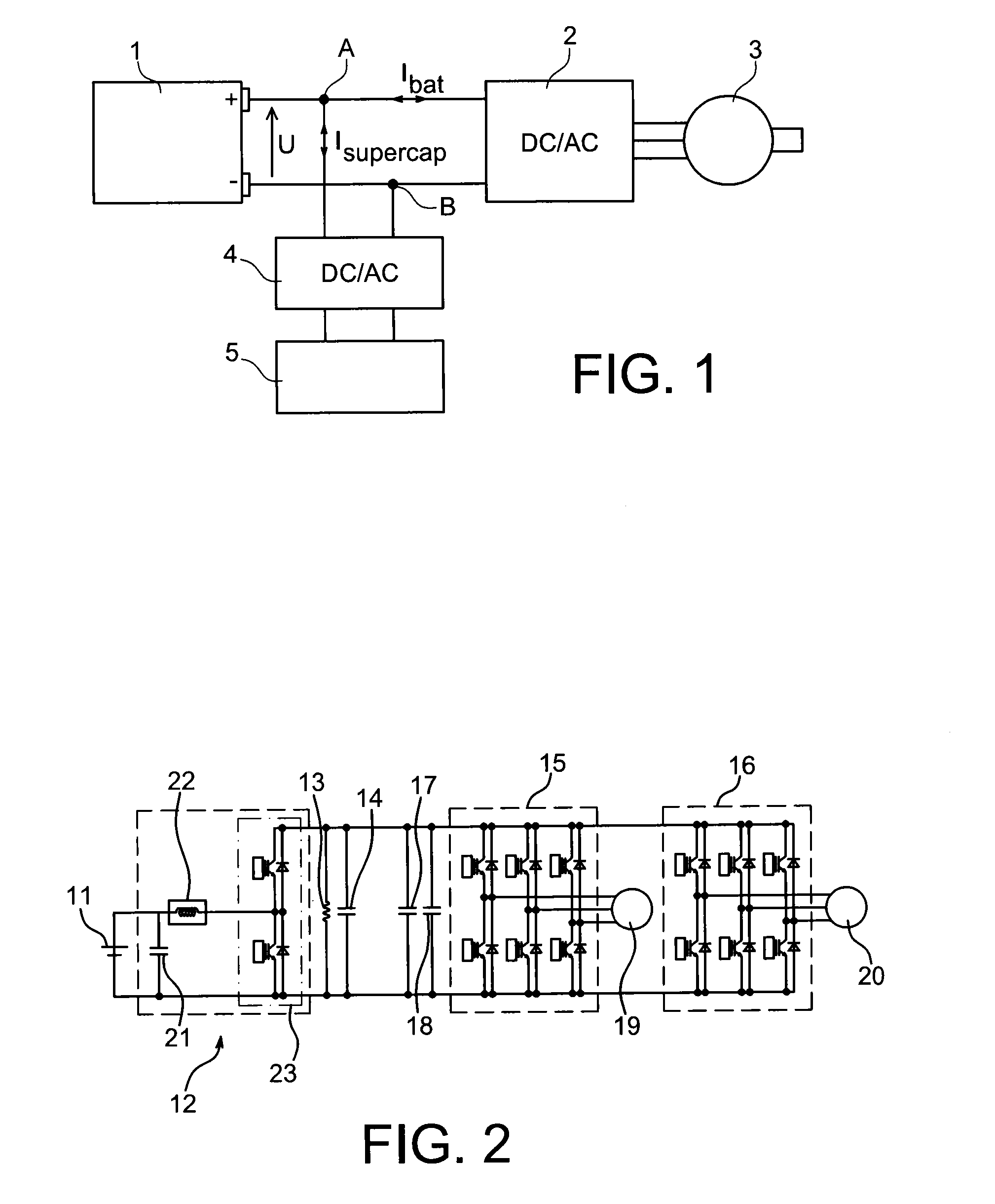
When the only energy source is a battery, it is very difficult to maintain the voltage on the DC bus when the load can absorb or output a high current during a very short time (for example during acceleration or braking of the vehicle).
The battery alone is also incapable of absorbing the entire braking energy during a very sho

Method used


Image

  • Two-directional current double-boost quadratic dc/dc converter
  • Two-directional current double-boost quadratic dc/dc converter
  • Two-directional current double-boost quadratic dc/dc converter

Examples


Example

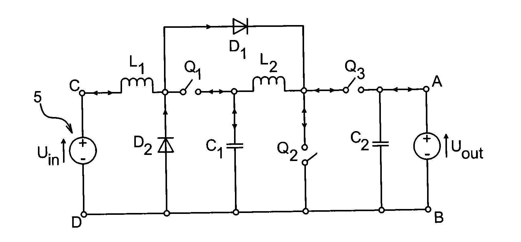
[0046]FIG. 4 is a diagram showing the topology of a current-reversible double-boost quadratic converter according to this invention. The converter shown in this figure forms the interface between the supercapacitor 5, the terminals (points C and D) of which receive an input voltage Uin, and points A and B (see FIG. 1) between which there is an output voltage Uout.

[0047]A first induction coil L1, a first switch Q1, a second induction coil L2 and a third switch Q3 are connected in series between points C and A. The connection between points D and B is a connection to the ground.

[0048]A diode D1 is connected in parallel onto elements Q1 and L2 installed in series. The anode of the diode D1 is on the same side as point C while its cathode is on the same side as point A.

[0049]A diode D2 is connected between the ground and the connection between elements L1 and The anode of diode D2 is connected to the ground.

[0050]A capacitor C1 is connected between the ground and the connection between ...


PUM


Abstract

A current reversible DC/DC double-boost quadratic converter, capable of performing high transformation ratios.

Description

TECHNICAL DOMAIN[0001]This invention relates to a DC / DC voltage converter, in other words a system designed to maintain the energy fluence between two voltage sources. The invention is particularly applicable to a converter of the type usually called a chopper, corresponding to average and high power applications.[0002]From the point of view of the electrical circuit, this type of converter may be considered as being a transformer of direct electrical magnitudes. There are two basic variants that define the type of DC / DC converter:[0003]if the output voltage is less than the input voltage, it is said to be a step-down DC / DC converter or buck converter,[0004]if the output voltage is greater than the input voltage, it is said to be a step-up DC / DC converter or boost converter.[0005]For this type of converter, the term two-directional current is used when the input or output current can be in either direction during operation of the converter.STATE OF PRIOR ART[0006]DC / DC step-up o...

Claims


Application Information

Patent Timeline
IPC IPC(8): H02M3/158
CPCB60L11/005B60L11/1868B60L2210/12B60L2210/14B60L2220/42H02M3/1582Y02T10/648H02M3/158Y02T10/7005Y02T10/7022Y02T10/7233Y02T10/7225Y02T10/7066H02M2001/007B60L50/40B60L58/20Y02T10/64Y02T10/70Y02T10/72H02M1/007
Inventor TOUZANI, YOUSSEFKEFSI, LAIDCHAMPENOIS, GERARDGAUBERT, JEAN-PAUL
Owner INST FR DU PETROLE
Learn More