Magnetic suspension counteraction flyback motor control system

A reaction flywheel and motor control technology, applied in the direction of single motor speed/torque control, electronic commutator, stop device, etc., can solve the problems of adjusting the driving voltage, increasing power consumption, waste, etc., and achieve simple driving circuit, Increase the overall power consumption, the effect of small input power interference

Inactive Publication Date: 2009-03-18
BEIHANG UNIV
View PDF0 Cites 22 Cited by
  • Summary
  • Abstract
  • Description
  • Claims
  • Application Information

AI Technical Summary

Problems solved by technology

The power supply voltage of the DC side of the driving part of this structure is constant, and the driving voltage applied to both ends of the stator winding of the permanent magnet brushless DC motor cannot be adjusted arbitrarily according to the needs. When the rotor speed of the permanent magnet brushless DC motor is low, the driving voltage is too high , the excessively high drive voltage energy can only be consumed through the energy consumption unit, and the power consumption increases, causing unnecessary waste; when increasing the output torque of the permanent magnet brushless DC motor, the only way to increase the permanent magnet brushless DC motor is to increase the input voltage. The driving voltage and power consumption of the magnetic brushless DC motor are relatively large

Method used


Image

  • Magnetic suspension counteraction flyback motor control system
  • Magnetic suspension counteraction flyback motor control system
  • Magnetic suspension counteraction flyback motor control system

Examples


Embodiment Construction

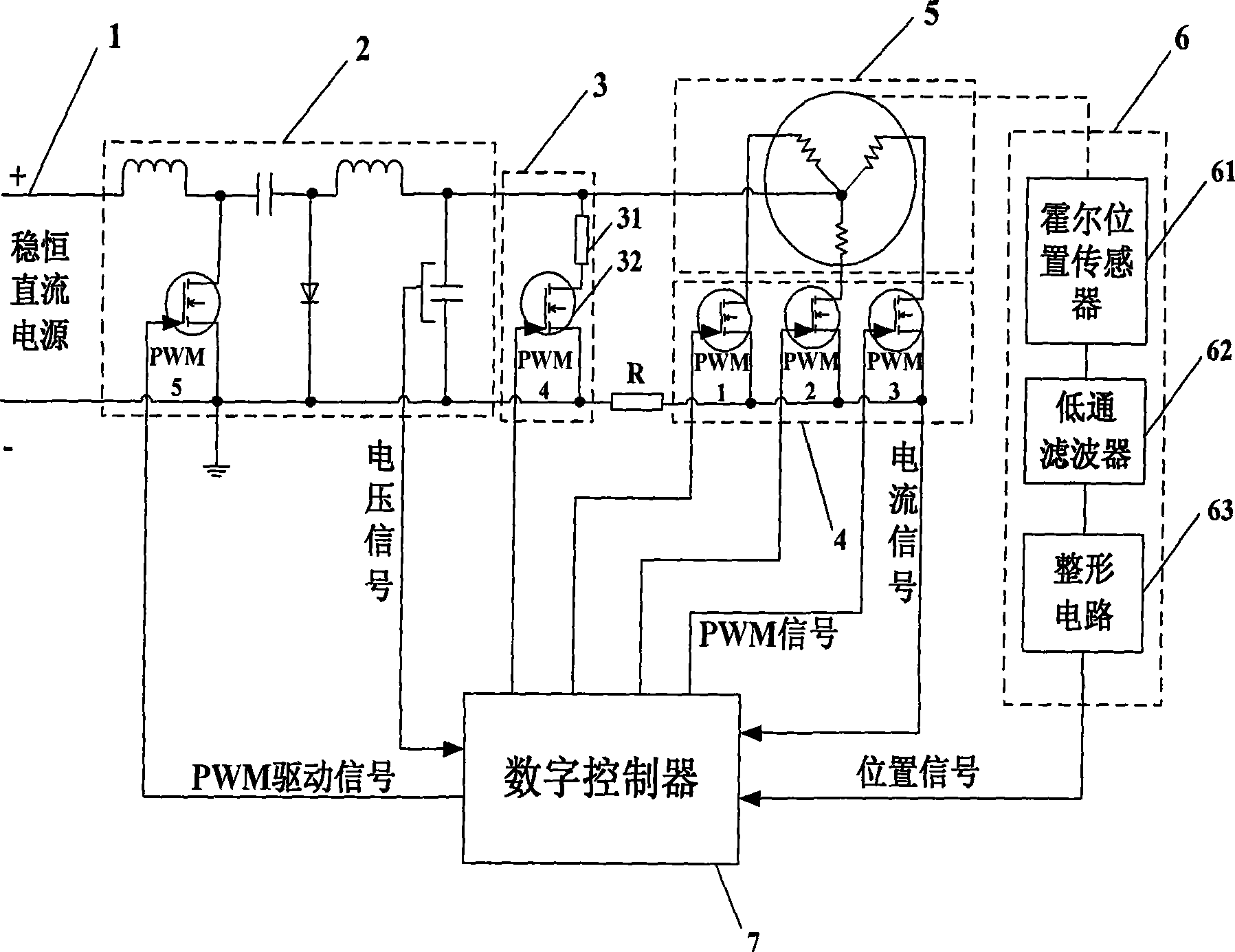
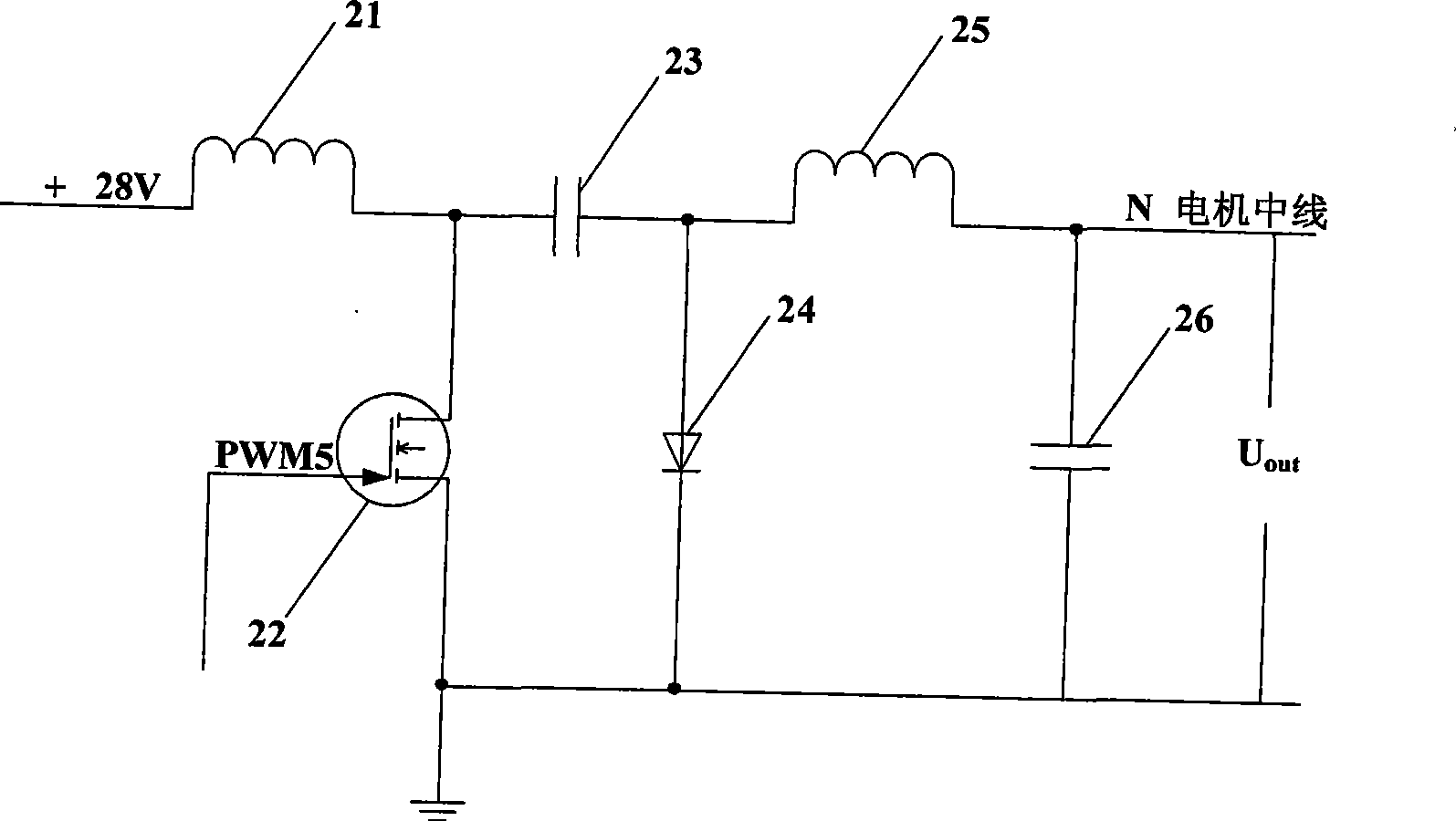
[0017] In this embodiment, the input steady DC voltage is 28V, the reference speed of the permanent magnet brushless DC motor 5 is designed to be 5000r / min, and the corresponding counter electromotive force of the permanent magnet brushless DC motor 5 is designed to be 40V, in order to make the Cuk buck-boost converter 2 Working in continuous current conduction mode, must meet 2Lf s / R≥(1-D) 2 , where L is the parallel equivalent value of the input filter inductance 21 and the output filter inductance 25, R is the equivalent resistance of the permanent magnet brushless DC motor 5, f s is the modulation frequency, and D is the conduction ratio of the self-shutoff power device. In the present invention, L is 0.25mH, R is 10Ω, and the PWM5 signal modulation frequency is set to 40K.

[0018] Such as figure 1As shown, this embodiment consists of a steady DC power supply 1, a Cuk buck-boost converter 2, an energy consumption unit 3, a three-phase star half bridge 4, a permanent m...


PUM


Abstract

The invention relates to a magnetic suspension reaction fly-wheel motor control system, which is mainly composed of a Cuk ascending and descending pressure converter, a permanent magnet brushless direct current motor, a three-phase star type half bridge, a digital controller, an energy consumption unit and other components. The system sends a detected position signal to the digital controller through a position measurement device, and the detected position signal is transformed into a PWM signal through the digital controller and is output to control the transformation ratio of the Cuk ascending and descending pressure converter, and the phase conversion and the speed adjustment of the energy consumption unit and the permanent magnet brushless direct current motor. The magnetic suspension reaction fly-wheel motor control system can carry out ascending and descending pressure conversion to steady direct current power supply voltage and can drive the permanent magnet brushless direct current motor according to rotation speed changes on rear time under the condition that input voltage is not changed, the phase conversion of the permanent magnet brushless direct current motor is controlled by the three-phase star type half bridge, the system dynamic performance is improved through increasing the output force moment factors of the permanent magnet brushless direct current motor and expanding the maximum accelerating moment of a magnetic suspension reaction fly wheel, simultaneously, total power consumption is not increased, and the magnetic suspension reaction fly-wheel motor control system has important application value to aerospace crafts with limited electric energy.

Description

technical field [0001] The invention relates to a magnetic levitation reaction flywheel motor control system, which can be used to expand the maximum acceleration torque of the attitude control actuators of spacecraft such as satellites under the condition of constant input voltage. Background technique [0002] Attitude control actuators of spacecraft such as satellites sometimes require a large output torque, and their drive components require low power consumption in order to make full use of the limited power energy of the spacecraft. In order to expand the maximum acceleration torque of the attitude control actuators of spacecraft such as satellites, it is usually achieved by increasing the torque coefficient of the permanent magnet brushless DC motor, but the back electromotive force will increase to several times of the steady DC power supply voltage, without increasing the input In the case of low voltage, step-up conversion is required to drive the permanent magnet ...

Claims


Application Information

Patent Timeline
Patent Type & Authority Applications(China)
IPC IPC(8): H02P6/08H02P6/16H02P6/24
Inventor 房建成孟姗姗李红汤继强周新秀朱娜
Owner BEIHANG UNIV
Why Eureka
Try Eureka