Heat pipe structure

Inactive Publication Date: 2013-05-23
ASIA VITAL COMPONENTS SHENZHEN CO LTD
View PDF2 Cites 1 Cited by
  • Summary
  • Abstract
  • Description
  • Claims
  • Application Information

AI Technical Summary

Benefits of technology

The invention aims to improve the heat transfer and dissipation efficiency of a heat pipe structure. It does this by reducing the pressure impedance of the heat pipe chamber, which increases the circulation efficiency of the working fluid.

Problems solved by technology

As a result, the vapor is likely to be obstructed by the liquid from spreading to the condensation end.
In this case, the vapor cannot be cooled to dissipate the heat.
Furthermore, the capillary structure disposed at the condensation end will cause pressure impedance to deteriorate the circulation of the liquid working fluid.
This will lower the heat transfer efficiency of the heat pipe.

Method used


Image

  • Heat pipe structure
  • Heat pipe structure
  • Heat pipe structure

Examples


Embodiment Construction

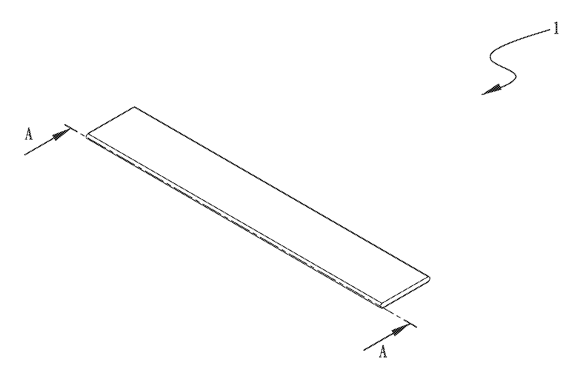
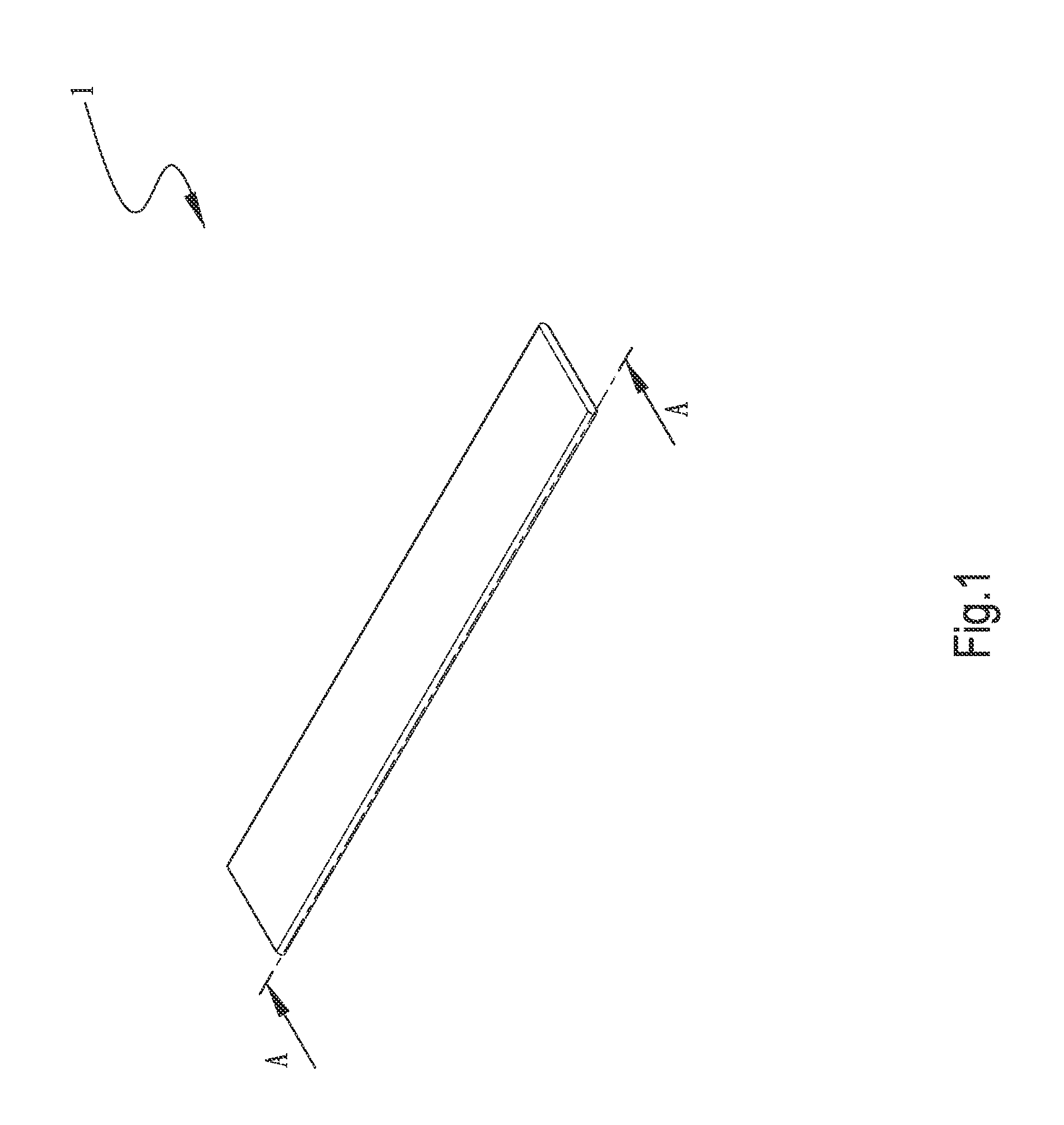
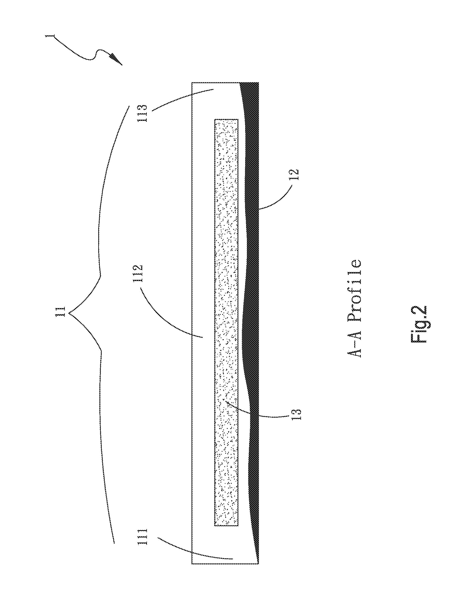
[0026]Please refer to FIGS. 1 and 2. FIG. 1 is a perspective view of a first embodiment of the heat pipe structure of the present invention. FIG. 2 is a sectional view of the first embodiment of the heat pipe structure of the present invention, taken along line A-A of FIG. 1. According to the first embodiment, the heat pipe structure of the present invention includes a tubular body 1.

[0027]The tubular body 1 has a chamber 11, a working fluid 12 and a first capillary structure 13. The chamber 11 is defined with at least one first section 111, a second section 112 and a third section 113. The first, second and third sections 111, 112, 113 are connected with each other. The first capillary structure 13 is disposed in the second section 112. The chamber 11 has a smooth inner wall.

[0028]The first capillary structure 13 is selected from a group consisting of sintered powder body, mesh body, fiber body and porous structure body. In this embodiment, the first capillary structure is, but not...


PUM


Abstract

A heat pipe structure includes a tubular body. The tubular body has a chamber, a working fluid and a first capillary structure. The chamber is defined with at least one first section, a second section and a third section. The first, second and third sections are connected with each other. The first capillary structure is disposed in the second section. By means of the above arrangement, the pressure impedance of the chamber of the heat pipe is lowered to greatly increase vapor-liquid circulation efficiency of the working fluid in the chamber.

Description

BACKGROUND OF THE INVENTION[0001]1. Field of the Invention[0002]The present invention relates generally to a heat pipe structure in which the pressure impedance of the chamber of the heat pipe is lowered to greatly increase vapor-liquid circulation efficiency of the working fluid in the chamber.[0003]2. Description of the Related Art[0004]A heat pipe has heat conductivity several times to several tens times that of copper, aluminum or the like. Therefore, the heat pipe has excellent performance and serves as a cooling component applied to various electronic devices. As to the configuration, the conventional heat pipes can be classified into heat pipes in the form of circular tubes and heat pipes in the form of flat plates. For cooling an electronic component of an electronic device that generates heat in operation, such as a CPU, preferably a flat-plate heat pipe is used in view of easy installation and larger contact area. To catch up the trend toward miniaturization of cooling mec...

Claims


Application Information

Patent Timeline
IPC IPC(8): F28D15/04
CPCF28D15/046F28D15/0233
Inventor WU, CHUN-MINGYANG, HSIU-WEI
Owner ASIA VITAL COMPONENTS SHENZHEN CO LTD
Why Eureka
Try Eureka