
Liquid Ejecting Head and Liquid Ejecting Apparatus

a liquid ejecting head and liquid ejecting technology, applied in printing and other directions, can solve the problems of insufficient adhesive pouring into this portion, inability to obtain sufficient bonded area in this portion, and inability to obtain sufficient adhesive in this portion, so as to prevent ink leakage and reduce costs

Active Publication Date: 2013-05-23
SEIKO EPSON CORP
View PDF1 Cites 23 Cited by
  • Summary
  • Abstract
  • Description
  • Claims
  • Application Information

AI Technical Summary

Benefits of technology

The invention provides a liquid ejecting head with multiple common liquid chambers that helps reduce costs while preventing ink leakage between the chambers. The configuration also includes a communication path that allows the empty liquid chamber forming portions to communicate with each other and define the common liquid chambers. This design reduces the size of the pressure generating unit and the overall cost of the liquid ejecting head. Additionally, the protective substrate prevents breakage of the pressure chamber forming substrate and pressure generator.

Problems solved by technology

However, such a silicon single-crystal substrate is costly compared to a substrate made of synthetic resin or the like.
However, a sufficient bonded area in this portion cannot be obtained, and the side surface of the head main body portion 54 which is formed of a plurality of component members stacked on top of one another is uneven and thus a sufficient amount of adhesive cannot be poured into this portion.

Method used


Image

  • Liquid Ejecting Head and Liquid Ejecting Apparatus
  • Liquid Ejecting Head and Liquid Ejecting Apparatus
  • Liquid Ejecting Head and Liquid Ejecting Apparatus

Examples


Embodiment Construction

[0029]An embodiment of the invention will now be described below with reference to the accompanying drawings. Although various limitations are made in the embodiment described below as preferred specific examples of the invention, it should be noted that the scope of the invention is not intended to be limited to this embodiment unless such limitations are explicitly mentioned hereinafter. In the following description, an ink jet printer (a type of liquid ejecting apparatus according to the invention) is used as an example of a liquid ejecting apparatus according to the invention.

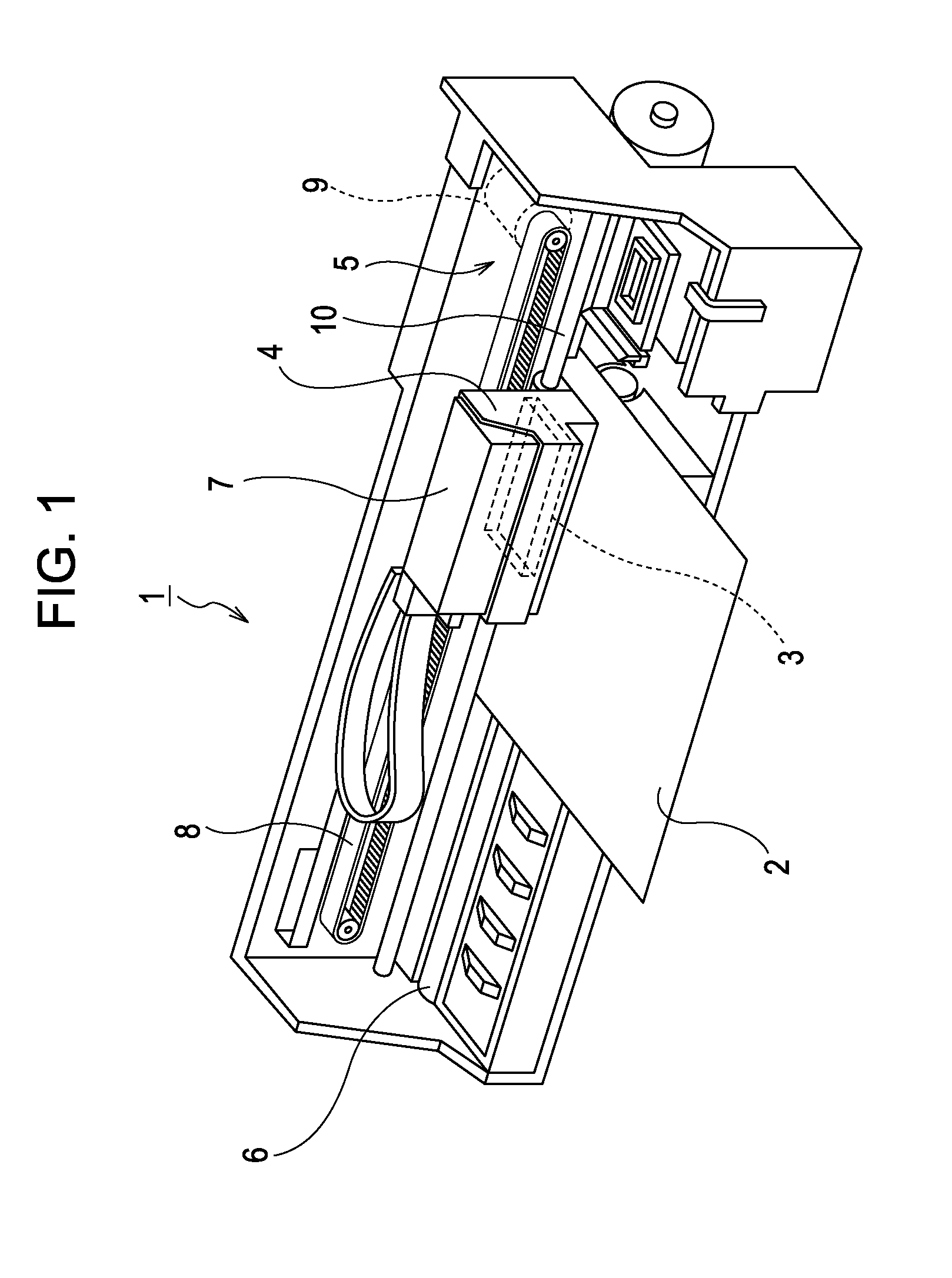
[0030]A configuration of a printer 1 will be described with reference to FIG. 1. The printer 1 is an apparatus that records an image or the like by ejecting liquid ink to a surface of a recording medium 2 such as a recording sheet (a type of landing target). The printer 1 includes a recording head 3 that ejects ink, a carriage 4 in which the recording head 3 is mounted, a carriage transfer mechanism 5 that ...


PUM


Abstract

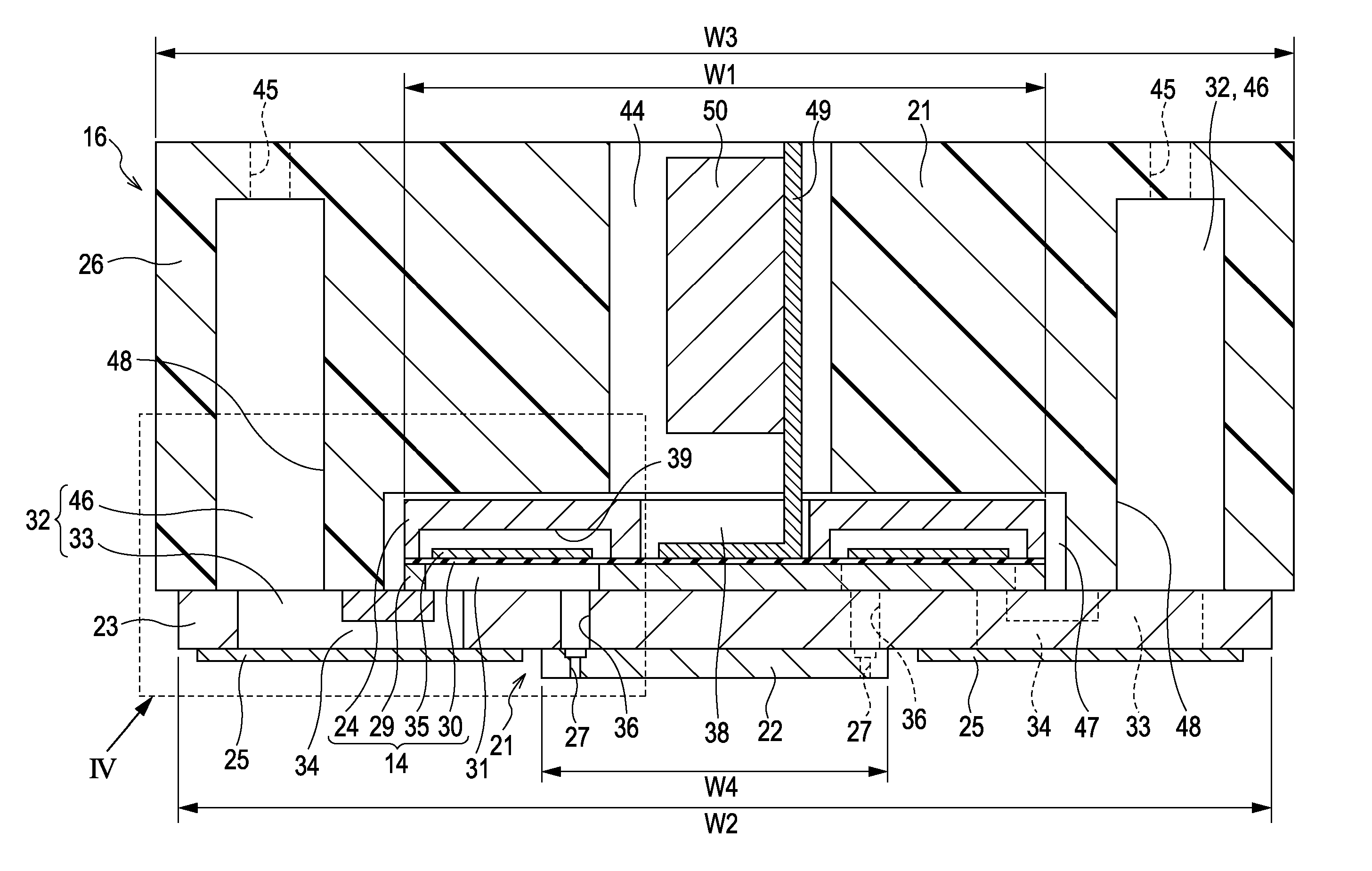
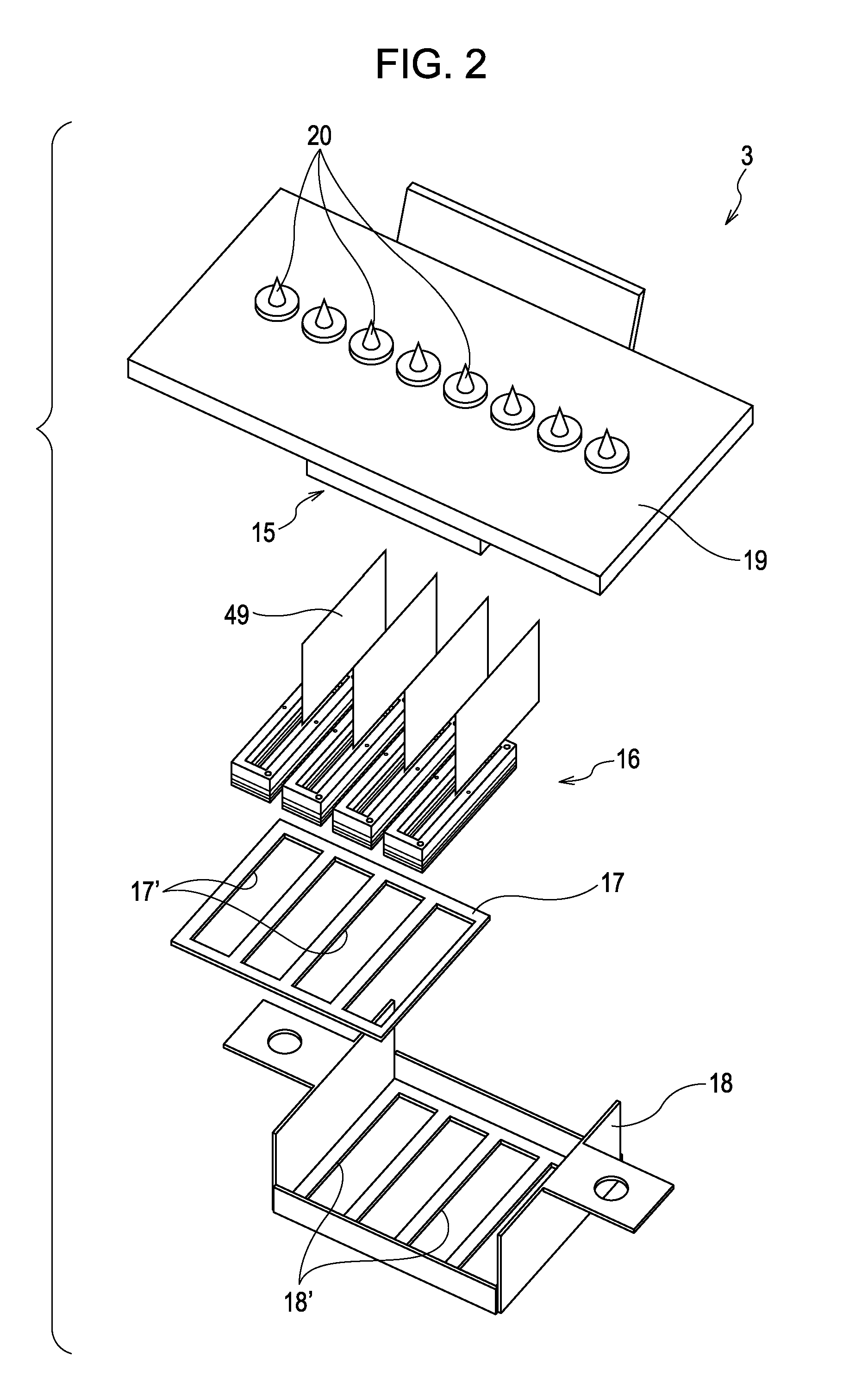
Liquid ejecting head comprises a unit head bonded to a communication substrate. A plurality of liquid chamber forming portions are formed in the unit case, along a first direction at positions that are separated by a partition wall. A plurality of empty liquid chamber portions and supply-side communication paths are formed in the communication substrate. The supply-side communication paths include a common communication path formed in a opposite side with a thin thickness portion left in the surface side of the communication substrate, and individual communication paths. With a surface of the partition wall and a surface of the thin thickness portion bonded together, the empty liquid chamber forming portions and the empty liquid chamber portions communicate with each other so as to define a plurality of common liquid chambers.

Description

[0001]This application claims a priority to Japanese Patent Application No. 2011-253644 filed on Nov. 21, 2011 which is hereby expressly incorporated by reference herein in its entirety.BACKGROUND[0002]1. Technical Field[0003]The present invention relates to liquid ejecting heads, such as ink jet recording heads, and to liquid ejecting apparatuses. In particular, the invention relates to a liquid ejecting head that includes a nozzle forming member in which a plurality of nozzles are provided in rows; a pressure generating unit including a pressure generator that causes pressure fluctuations in a pressure chamber; a communication member in which an empty liquid chamber portion that is to be a portion of a common liquid chamber, and a supply-side communication path that allows communication between the empty liquid chamber portion and the pressure chamber are formed; and a case member to which the communication member to which the nozzle forming member and the pressure generating unit...

Claims


Application Information

Patent Timeline
Patent Type & Authority Applications(United States)
IPC IPC(8): B41J2/045
CPCB41J2/055B41J2/14233B41J2/175B41J2002/14306B41J2002/14241B41J2002/14491B41J2002/14419B41J2/1433
Inventor WATANABE, SHUNSUKEMIYATA, YOSHINAOOGUCHI, SATOSHIOKUI, HIROAKI
Owner SEIKO EPSON CORP
Learn More