Snap and electrode assembly for a heart rate monitor belt

a heart rate monitor and electrode assembly technology, applied in bioelectric signal measurement, medical science, therapy, etc., can solve the problems of reduced breathability of these locations, loose electrical conductors on the surface of fabric, and discomfort against the skin

Active Publication Date: 2013-05-23
SUUNTO OY
View PDF3 Cites 69 Cited by
  • Summary
  • Abstract
  • Description
  • Claims
  • Application Information

AI Technical Summary

Benefits of technology

[0026]A sensory may comprise a construction of at least three layers, in which there is a substrate layer that remains against the skin, a first insulating layer, and a conductor layer. Furthermore, another insulating layer can be arranged on the second surface of the conductor layer as a fourth layer. The task of the insulating layer is to prevent liquid, for example, perspiration that accumulates in the substrate during exercise, from reaching the conductor layer and thus to prevent an electrical contact arising with the signal conductor and undesirable interference connecting with the electrode signal.
[0027]In the constructions provided herein, it is possible to combine flexibility of the structure and reliability of the signalling with the sensory's comfort in use. In particular, they permit the use of durable textiles substrates of a tested comfort, directly against the skin either entirely or nearly entirely in the whole area of the sensory. The transmission conductor of the signal is protected against stress, moisture, and electrical interference on the second side of the textile.
[0028]The constructions can also be manufactured entirely form the inner surface of the substrate, in which case the outer surface coming against the user remains untouched, except for the electrode openings. Thus, for example, the comfort and breathability of the textile substrate remain good, even at the conductors. The conductors also remain behind the textile layer, well protected from mechanical stress.

Problems solved by technology

However, the laminate then remains on the surface of the product at the conductors, so that the breathability of these locations is reduced and they may feel uncomfortable against the skin.
This solution also has a problem with the placing of the signal transmission conductors relative to the fibre material, particularly with creating both reliable contacts with the electrodes for them and good electrical insulation.
However, the electrical conductors remain loose of the surface of the fabric and liable to mechanical stresses acting on them.
Though it can be attached to many different pieces of apparel, it does not eliminate the problem of discomfort when using traditional heart rate bands.
Due to the existing technology and methods for detachably connecting telemetric transmitters it has not been realistic to incorporate heart rate monitor electrodes in to typical garments.
In fact, the primary road block to such incorporation has been the size and bulkiness of the standard garment snaps.
No clothing manufacture, nor consumer, has wanted 4 mm protrusions from their garments such as tops, shirts and sports bras.
As such, it would not be economical to wholly redesign the male portions of telemetric transmitters and the method in which they connect to an object having the necessary electrodes for measuring a user's heart rate.
However, several critical issues arise when attempting to merely minimize the existing standardized snap.
The main issue is the integrity of the connection between the male stud and the snap.
Any amount over movement of the male stud within the snap will create electrical noise which makes difficult to impossible to accurately measure parameters such as a user's heart beat.
Additionally, as a user is typically involved in strenuous activity while utilizing the product, the connection needs to withstand, and support the telemetric transmitter during such activity.
Further yet, users typically sweat while undergoing strenuous activity wearing the product.
Similarly, the problem is compounded for users who wish to utilize a heart rate monitor under water, for example while swimming or diving.
Therefore, there exist numerous challenges in the art to the development of a means of detachably connecting a telemetric transmitter to a garment having electrodes for monitoring a user's heart beat which aims to satisfy user's need, the garment manufacturer's needs and the needs of telemetric transmitter manufactures.

Method used


Image

  • Snap and electrode assembly for a heart rate monitor belt
  • Snap and electrode assembly for a heart rate monitor belt
  • Snap and electrode assembly for a heart rate monitor belt

Examples


Embodiment Construction

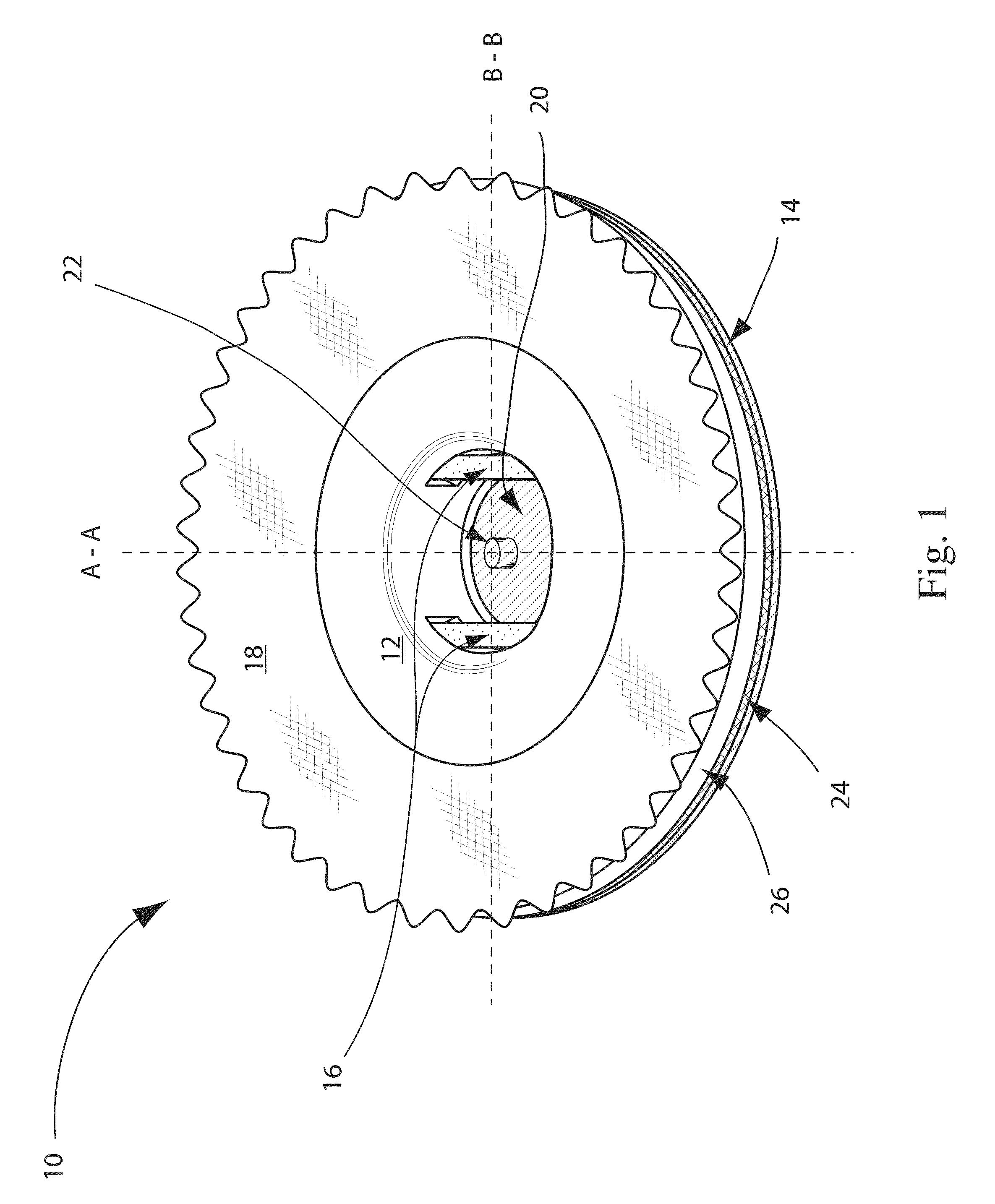
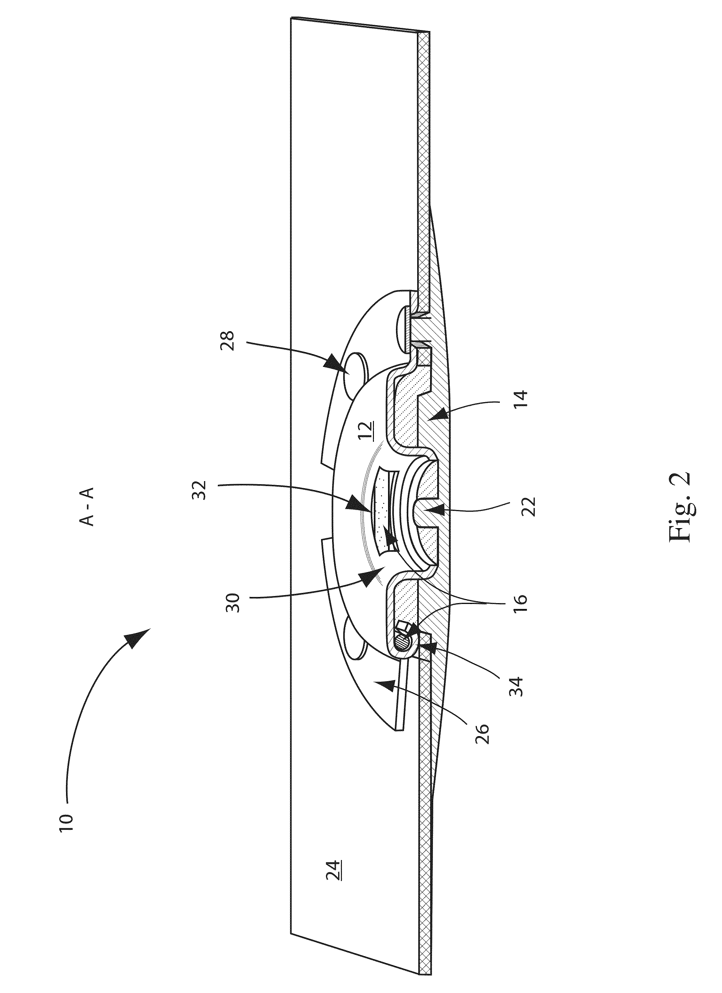
[0046]A snap 10 in accordance with an embodiment of the present invention is shown in FIG. 1. The snap is shown integrated within a material 18. As can be seen from the figure, the upper cap portion 12 of the snap 10 is essentially flush with the material 18, i.e. there is no significant protrusion. Such an integrated snap design is highly desirable when transitioning from stand alone heart rate monitor belts worn in addition to regular clothing to integrating the functionality of a heart rate monitor in to clothing itself.

[0047]As discussed herein, a heart rate monitor belt is the combination of electrodes and snaps in such an arrangement that they can be used to determine, measure and / or monitor the heart beat of an individual or animal wearing the belt. A heart rate monitor belt may be a standalone article in the form of, for example, a belt having a plurality of electrodes connected to a pair of snaps which can be worn, for example around the torso of a user. Additionally, a hea...


PUM


Abstract

The present invention relates generally to a thin, low thickness snap integrated within or built within a heart rate monitor belt or snap and electrode assebly. The snap can be integrated or built directly in to a heart rate monitor belt. Furthermore, the heart rate monitor belt can be integrated within a textile or garment, for example a compression shirt, sports bra or cycling shorts. The snap can be flushly integrated into the belt or garment such the snap does not take away from the general wearability of the heart rate monitor belt or garment.

Description

FIELD OF INVENTION[0001]The present invention relates generally to a snap and electrode assembly for use in a heart rate monitor belt. More particularly, embodiments of the present snap are particularly well suited for receiving, holding and enabling an electrical connection with a male end of a telemetric device. Examples of the present snap and electrode assembly are integrated within a heart rate monitor belt.BACKGROUND OF THE INVENTION[0002]Traditional heart-rate meter heart rate bands and heart rate belts generally comprise a body made of plastic, on the surface of which there are two local electrodes to be placed against the chest. Electronics for transmitting a heart rate signal, typically to a wristop device, are built into the plastic body. Conductors from the electrodes to the electronics also run inside the body, which is generally attached against the chest with the aid of a flexible band.[0003]Because plastic heart rate bands are relatively thick and can feel uncomforta...

Claims


Application Information

Patent Timeline
Patent Type & Authority Applications(United States)
IPC IPC(8): A61B5/0245A61B5/00A61B5/0408A61B5/0416A61B5/274
CPCA61B5/0245A61B5/0416A61B5/6831A61N1/0484A61B5/6804A61N1/22A61B5/04085A61B5/274A61B5/282A61B5/28
Inventor PERNU, KIMMOSELBY, TAPIOLINDBERG, PHILLIPMANNI, JUKKALILJEMARK, JORMASAVOLAINEN, TAPIOPUTKINEN, HANNUAKKILA, JARIRAHKONEN, SATULINDMAN, ERIK
Owner SUUNTO OY
Why Eureka
Try Eureka