
Touch enabled device drop zone

a technology of touch enabled devices and drop zones, which is applied in computing, instruments, electric digital data processing, etc., can solve the problems that many tablet devices do not provide an effective approach for users to perform operations, and achieve the effect of expanding the size of the drop zone region 106

Inactive Publication Date: 2013-05-23
ADOBE INC
View PDF9 Cites 42 Cited by
  • Summary
  • Abstract
  • Description
  • Claims
  • Application Information

AI Technical Summary

Benefits of technology

The patent describes a touch-enabled device that allows for easy movement and processing of objects within a graphical user interface. There is a display region for displaying objects and a separate drop zone region for adding or processing objects. The device can position objects within the drop zone and perform operations on them, such as dragging or selecting an associated operation based on the location within the drop zone. This technology simplifies the user's experience and allows for more efficient use of the device's capabilities.

Problems solved by technology

However, many tablet devices do not provide an effective approach for users to perform operations that would typically be performed on a conventional computing device, such as cut, copy, paste, etc.

Method used


Image

  • Touch enabled device drop zone
  • Touch enabled device drop zone
  • Touch enabled device drop zone

Examples


Embodiment Construction

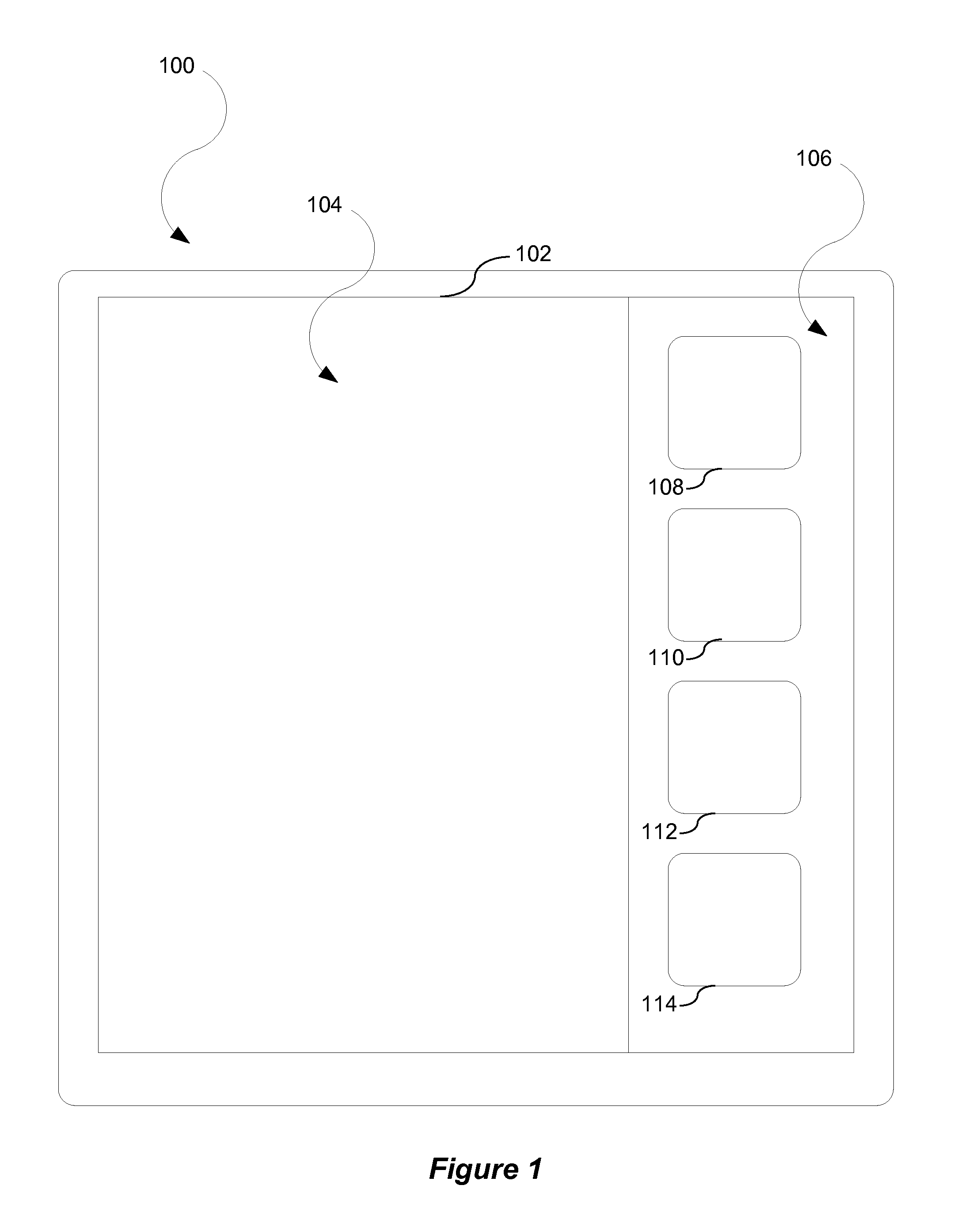
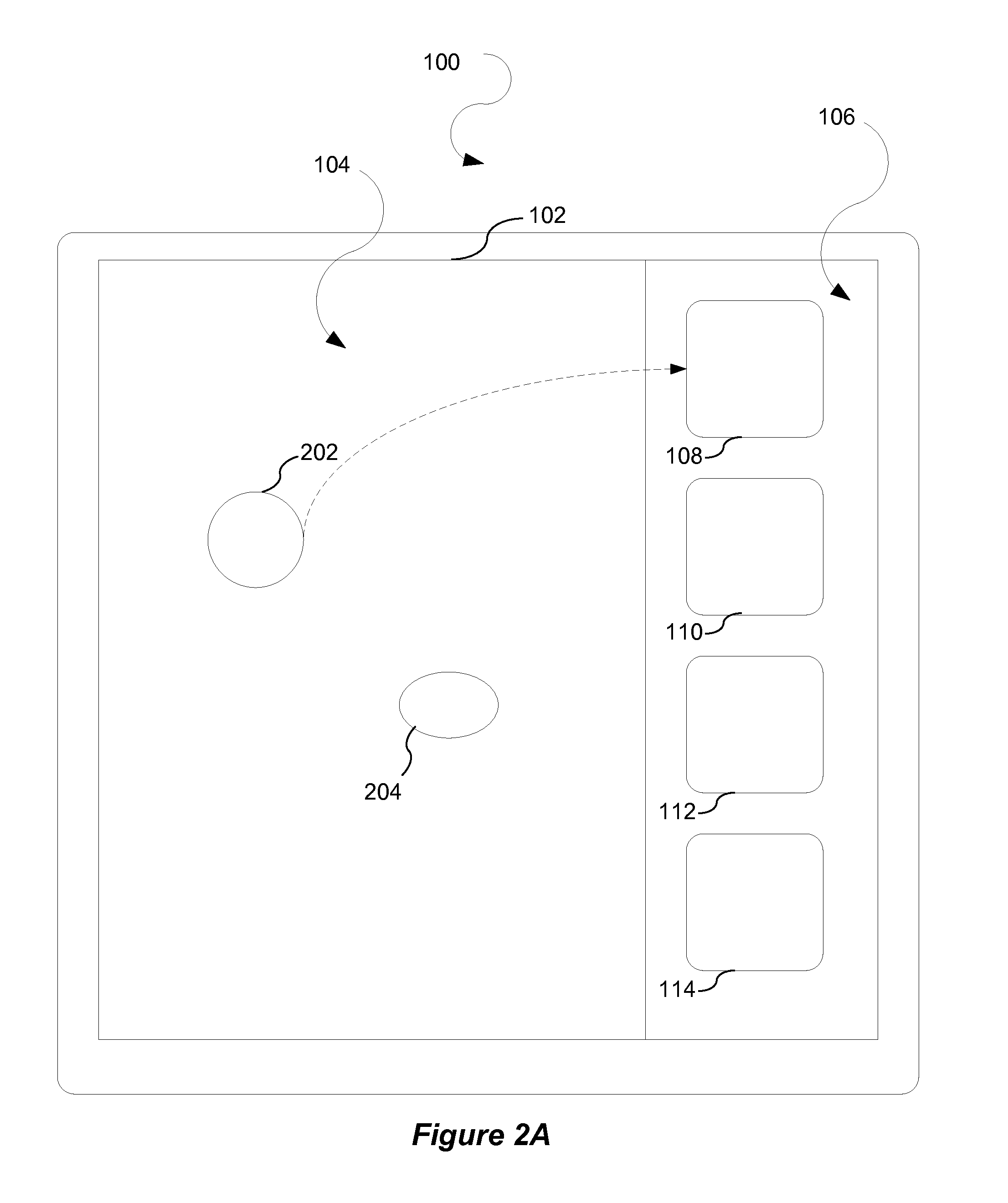
[0023]A portion of a touch enabled device graphical user interface (“GUI”) is dedicated to allowing a user to perform certain functionality. This portion is referred to herein is a drop zone region. The user may move an object to the drop zone region to perform various functions. For example, the user may drag and drop an object to the drop zone region to perform a cut, copy, paste, delete, share, or like operation on the object. In one embodiment, a user may drag a plurality of objects to the drop zone and then perform batch processing on the plurality of objects. For example, if a cut operation is to be performed on a group of objects, the user may drag all of the objects to the drop zone and then provide a single cut command to cut all of the objects in the drop zone rather than having to perform the cut operation on each individual object. In an alternative embodiment, a user may drag an object to a particular sub-region of the drop zone to perform function. For example, a tile ...


PUM


Abstract

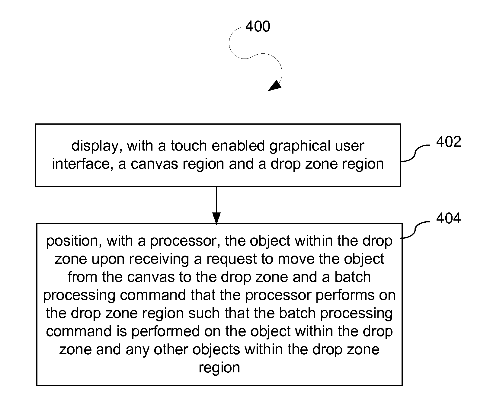
A touch enabled device includes a touch enabled graphical user interface that displays a canvas region and a drop zone region. The canvas region displays an object. The drop zone region displays an area that is distinct from the canvas region. Further, the touch enabled device includes a processor that positions the object within the drop zone upon receiving a request to move the object from the canvas to the drop zone and a batch processing command that the processor performs on the drop zone region such that the batch processing command is performed on the object within the drop zone and any other objects within the drop zone region.

Description

BACKGROUND[0001]1. Field[0002]This disclosure generally relates to computing devices. More particularly, the disclosure relates to managing functionality for a touch enabled device.[0003]2. General Background[0004]Conventional computing devices allow for various functions, e.g., cut, copy, paste, etc., to be performed with various commands. For example, a user may press a combination of keyboard keys such as “Ctrl” and “X” to perform a cut operation. As another example, a user may perform a right click with a mouse device to select a cut operation.[0005]Recent developments have led to an increase in demand for tablet devices. Many tablet devices are touch enabled, which allows a user to perform a variety of operations by touching a screen of a tablet device with one or more fingers, a stylus, etc. However, many tablet devices do not provide an effective approach for users to perform operations that would typically be performed on a conventional computing device, such as cut, copy, p...

Claims


Application Information

Patent Timeline
Patent Type & Authority Applications(United States)
IPC IPC(8): G06F3/048
CPCG06F3/0488G06F3/04817G06F3/0486
Inventor TIJSSEN, REMON
Owner ADOBE INC
Learn More