Hull cleaner

Active Publication Date: 2013-05-30
HIGGINS JOHN ANDREW +1
View PDF4 Cites 4 Cited by
  • Summary
  • Abstract
  • Description
  • Claims
  • Application Information

AI Technical Summary

Benefits of technology

[0003]According to one aspect of the invention there is provided a boat hull cleaner comprising a pole having at least two parts which can be set at an angle with respect to one another, a float, and a brush, the float having a buoyancy portion which gives a minimum buoyancy to the float; the float having an opening or openings arranged to admit water into the float when it is ti

Problems solved by technology

A problem with yachts, launches and other pleasure craft is that the parts which are submerged beneath the water

Method used


Image

  • Hull cleaner
  • Hull cleaner
  • Hull cleaner

Examples


Embodiment Construction

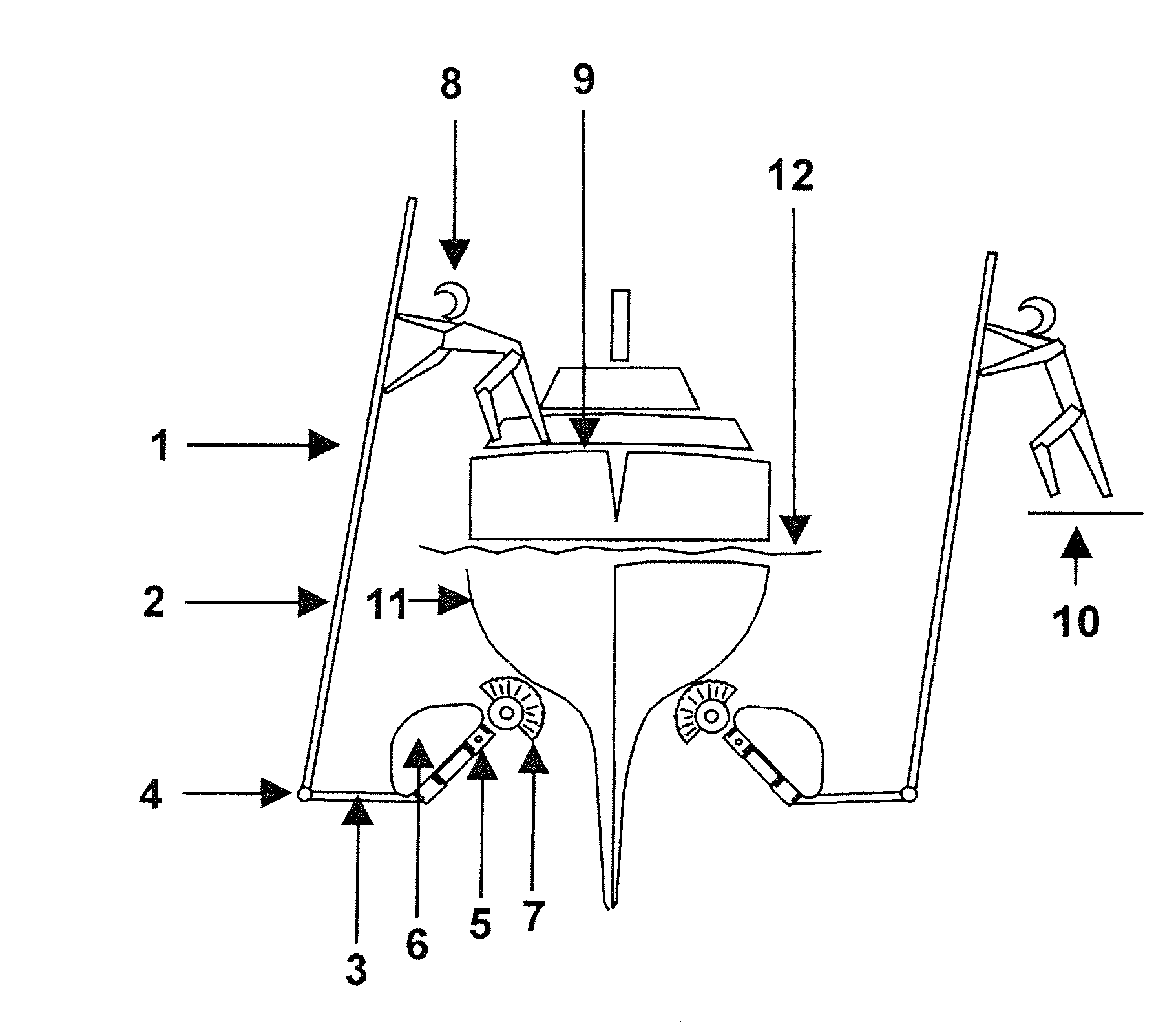
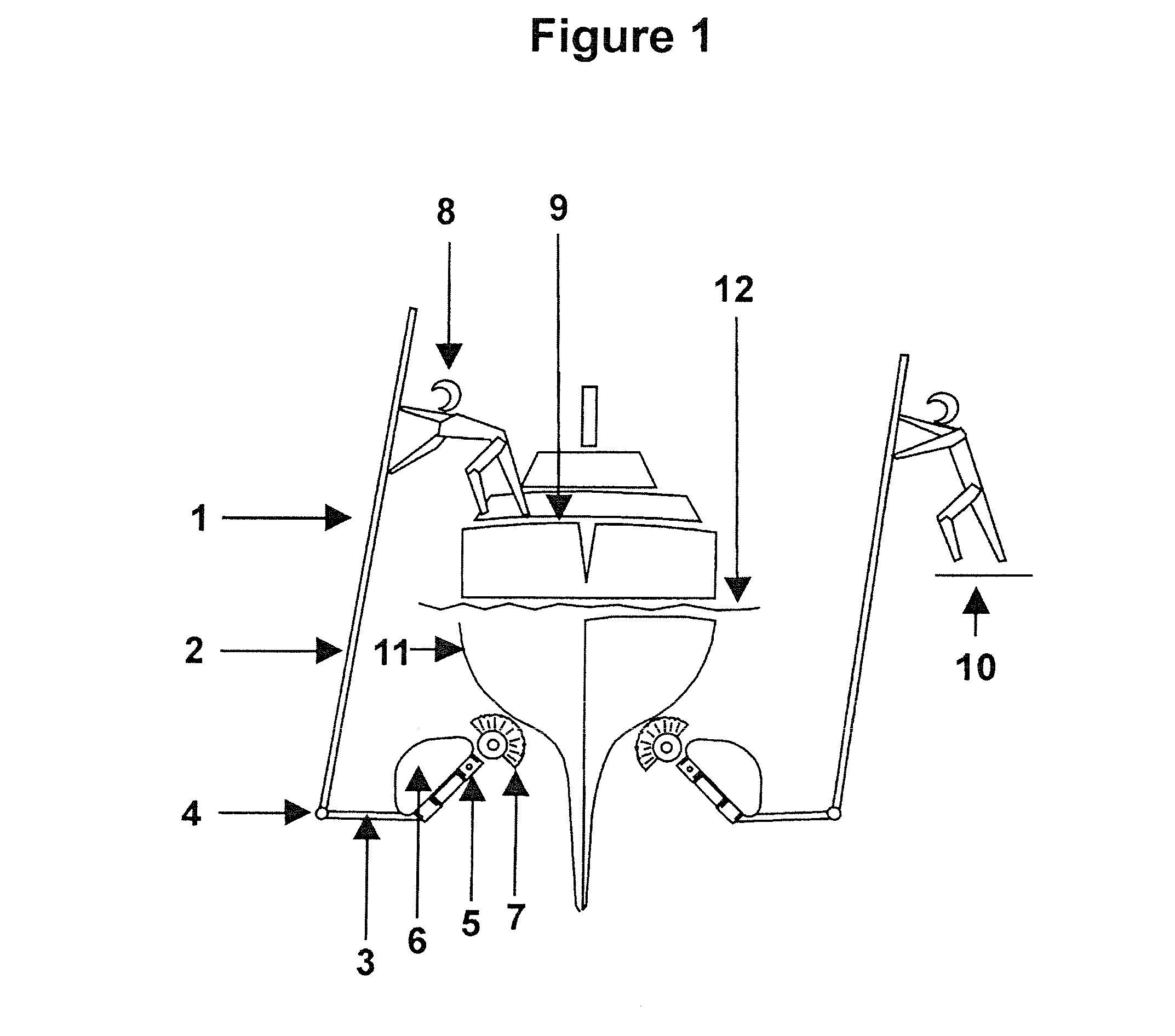
[0021]Referring to FIG. 1, the hull cleaner 1 comprises a telescoping pole in two parts 2 and 3 with a knuckle joint 4 therebetween. The joint 4 allows the two parts of the pole 2 and 3 to be set at varying angles with respect to one another, for example at an angle of between 0° and 260°. The smaller part of the pole 3 is connected to a permanently angled support shaft 5, which in turn connects to a float 6 and a scrubbing brush 7. The brush 7 is “half round” in the sense that its bristles have a semi-circular configuration as shown. In other embodiments the brush bristles may have an alternative arc-like configuration.

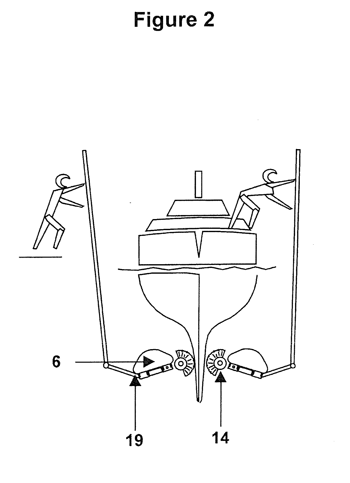
[0022]With further reference to FIG. 1, a person 8 can stand on the deck of a boat 9, or on a jetty 10 next to the boat, and manipulate the hull cleaner by hand to scrub the boat's hull 11 beneath the waterline 12. The two parts of the pole 2 and 3 are set at the most desirable angle for achieving this and, as shown, the brush 7 is angled upwards. Referring to FIG. 2...


PUM


Abstract

A boat hull cleaner comprises a pole having at least two parts 2, 3 which can be set at an angle with respect to one another, a float 6, and a brush 7, the float having a buoyancy portion which gives a minimum buoyancy to the float. The float has an opening or openings arranged to admit water into the float when it is tilted while under water with the result that effective buoyancy of the float is adjusted. The hull cleaner is formed such that when it is in use a human operator can hold one end of the pole from above water level and move it to manipulate the float and the brush beneath water level such that the float encourages the brush against a boat hull to assist the operator to clean the hull.

Description

FIELD OF INVENTION[0001]A preferred form of this invention relates to a hull cleaner for use with water vessels, for example pleasure craft.BACKGROUND[0002]A problem with yachts, launches and other pleasure craft is that the parts which are submerged beneath the water for long periods of time can become covered in undesirable matter, for example with algae or other marine life. It is accordingly an object of a preferred form of the invention to go at least some way towards dealing with this.SUMMARY OF INVENTION[0003]According to one aspect of the invention there is provided a boat hull cleaner comprising a pole having at least two parts which can be set at an angle with respect to one another, a float, and a brush, the float having a buoyancy portion which gives a minimum buoyancy to the float; the float having an opening or openings arranged to admit water into the float when it is tilted while under water with the result that effective buoyancy of the float is adjusted; the hull c...

Claims


Application Information

Patent Timeline
IPC IPC(8): A47L9/28B63B59/08A46B9/02
CPCB63B59/08
Inventor HIGGINS, JOHN ANDREWSHEAP, MICHAEL ANDREW
Owner HIGGINS JOHN ANDREW
Why Eureka
Try Eureka