

Touch Sensor Back Plane Ground Connection
a touch sensor and back plane technology, applied in the direction of riveted connection, instrument, cable junction, etc., can solve the problems of touch sensor failure, touch sensor failure altogether, touch sensor misrepresentation, etc., and achieve the effect of reliable ground connection
- Summary
- Abstract
- Description
- Claims
- Application Information
AI Technical Summary
Problems solved by technology
Method used
Image

Examples
embodiments
First Exemplary Embodiment
[0042]According to a first exemplary embodiment, a conductive film or tail can be bent according to FIGS. 4A, 4B, 4C, and 4D to connect backplane 404 to device chassis 402. FIG. 4A illustrates tail 406 in a first configuration. FIGS. 4B and 4C represent intermediate configurations of tail 406. FIG. 4D represents a fourth configuration of tail 406. Tail 406 can transition from one configuration to another configuration by bending it along its bend lines.
[0043]In the first configuration, tail 406 lies flat to the right of back plane 404. As illustrated in FIG. 4A, tail 406 can have three bend lines 408, 410, and 412. Bend lines 408 and 410 can be critical bends. Bend line 412 can be a non-critical bend. On either side of bend line 412 are two holes 414 and 416 which can accommodate a screw (not shown). The hatched region can correspond to device chassis 402.
[0044]FIG. 4B illustrates tail 406 in a second configuration. To transition from the first configuratio...
second exemplary embodiment
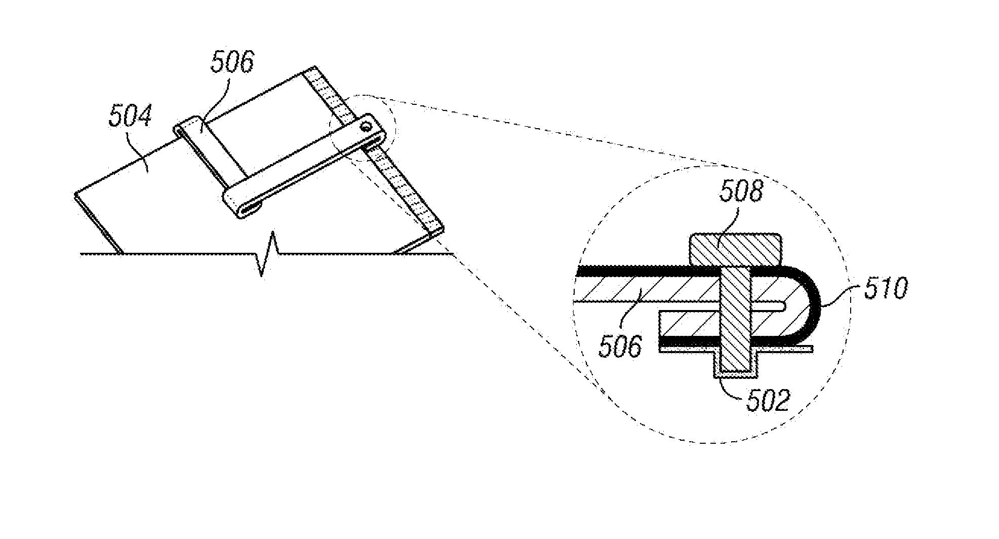
[0062]In a second exemplary embodiment, conductive film or tail 706 can be bent according to FIGS. 7A and 7B to connect back plane 704 to device chassis 702. FIG. 7A illustrates tail 706 in a first configuration. FIG. 7B illustrates tail 706 in a second configuration. Tail 706 can be bent from right to left along bend line 708 to transition from the first configuration of FIG. 7A to the second configuration of FIG. 7B. As illustrated in FIG. 7B, tail 706 can rest on back plane 704. Bend line 708 can be a critical bend. A screw hole 710 is located at one end of tail 706.
[0063]In the configuration of FIG. 7B, a screw (not shown) can be inserted in hole 710 to fasten tail 706 to device chassis 702. Because tail 706 is connected to back plane 704 on its other end, fastening tail 706 to device chassis 702 can create an electrical connection between back plane 704, tail 706, and device chassis 702.
[0064]FIG. 8 illustrates a top of view of the tail from FIG. 7B and provides a detailed view...
third exemplary embodiment
[0076]In a third exemplary embodiment, conductive film or tail 1006 can be bent according to FIGS. 10A, 10B, and 10C to connect backplane 1004 to device chassis 1002. FIGS. 10A, 10B, and 10C illustrate tail 1006 in three different configurations. Tail 1006 can transition from one configuration to another configuration by bending it along its bend lines.
[0077]In the first configuration, tail 1006 rests in a flattened configuration to the right of back plane 1004. Tail 1006 can have two bend lines 1008 and 1010. Bend line 1008 is a critical bend, and bend line 1010 is a non-critical bend. On either side of bend line 1010 are two holes 1012 and 1014 which can accommodate a screw (not shown). The hatched region can correspond to device chassis 1002.
[0078]FIG. 10B illustrates tail 1006 in a second configuration. To transition from the first configuration to the second configuration, tail 1006 can be folded from right to left along bend line 1008 such that tail 1006 rests along back plane...
PUM
 Abstract
Description
Claims
Application Information