Image forming apparatus

a technology of image forming apparatus and feed cassette, which is applied in the direction of electrographic process apparatus, thin material processing, instruments, etc., can solve the problems of reducing the size of the image forming apparatus, improper supply of sheets to the feed cassette, etc., and achieves the effect of compact image forming apparatus

Active Publication Date: 2013-05-30
RICOH KK
View PDF2 Cites 8 Cited by
  • Summary
  • Abstract
  • Description
  • Claims
  • Application Information

AI Technical Summary

Benefits of technology

[0011]In view of the foregoing, illustrative embodiments of the present invention provide a novel image forming apparatus in which recording media are properly supplied to a sheet feed cassette and an installation space for a stopper mechanism is minimized and thus making the image forming apparatus more compact.

Problems solved by technology

However, because the above-described configuration allows supply of the sheets without detaching the sheet feed cassette from the image forming apparatus, the sheets may be improperly supplied to the sheet feed cassette.
However, the stopper mechanism requires a large installation space especially in a width direction of the image forming apparatus perpendicular to a direction of withdrawal of the sheet feed cassette from the image forming apparatus, thereby preventing reduction in the size of the image forming apparatus.

Method used


Image

  • Image forming apparatus
  • Image forming apparatus
  • Image forming apparatus

Examples


Embodiment Construction

[0043]In describing illustrative embodiments illustrated in the drawings, specific terminology is employed for the sake of clarity. However, the disclosure of this patent specification is not intended to be limited to the specific terminology so selected, and it is to be understood that each specific element includes all technical equivalents that operate in a similar manner and achieve a similar result.

[0044]Illustrative embodiments of the present invention are now described below with reference to the accompanying drawings. In a later-described comparative example, illustrative embodiment, and exemplary variation, for the sake of simplicity the same reference numerals will be given to identical constituent elements such as parts and materials having the same functions, and redundant descriptions thereof omitted unless otherwise required.

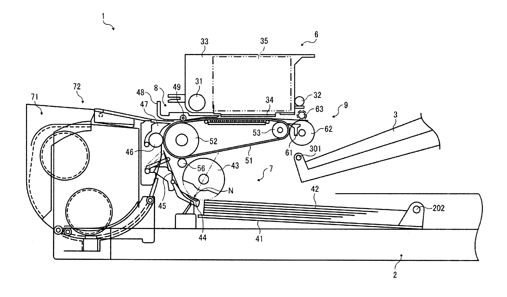
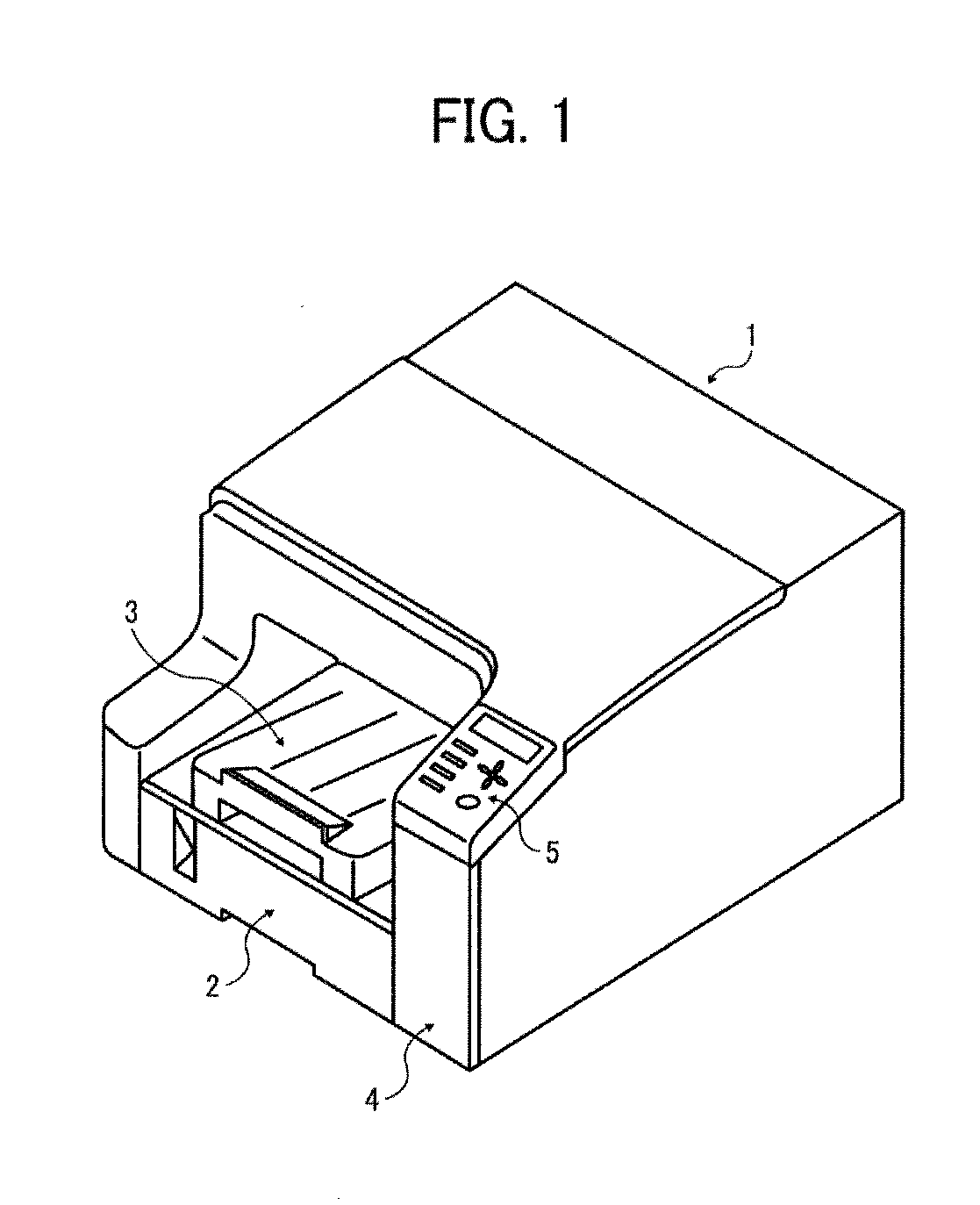
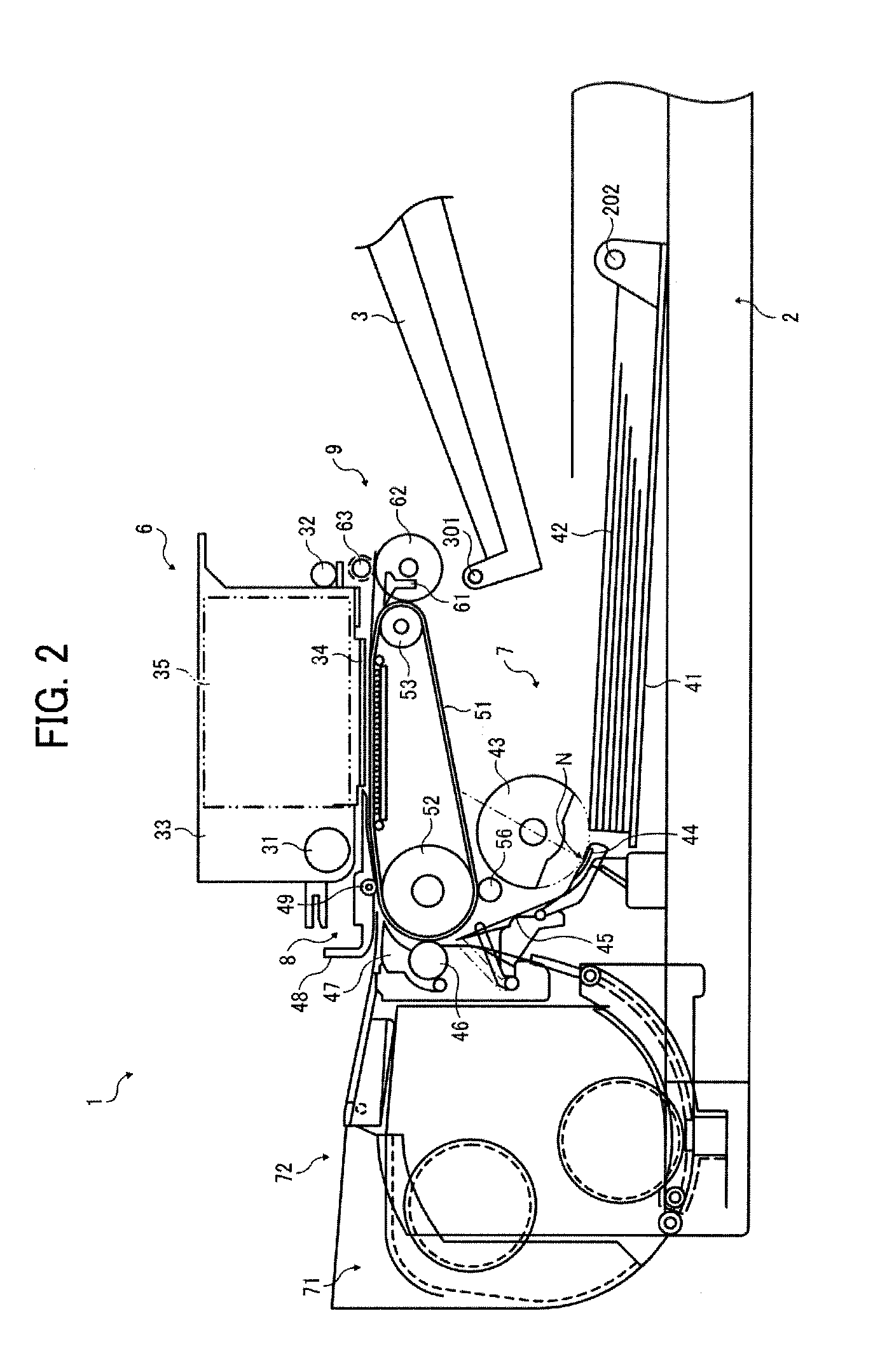
[0045]Image forming apparatuses hereinafter described form an image on a recording medium, such as paper, string, fiber, cloth, lather, metal, pla...


PUM


Abstract

An image forming apparatus including a sheet container, a sheet stacking member to closably open the sheet container; a restriction unit to restrict a swinging movement of the sheet stacking member, and a stopper mechanism to restrict insertion of the sheet container into the image forming apparatus in a state in which the sheet stacking member swings open from the sheet container. The stopper mechanism includes a stopped member provided to the sheet container and being movable vertically along the swinging movement of the sheet stacking member, and a stopper member provided to the image forming apparatus and being contactable with the stopped member. The stopped member includes a stopped surface contacted by the stopper member in a state in which the stopped member is lifted; and a switching surface adjacent to the stopped surface and vertically moving the stopped member by contact against the stopper member.

Description

CROSS-REFERENCE TO RELATED APPLICATION[0001]This patent application is based on and claims priority pursuant to 35 U.S.C. §119 to Japanese Patent Application No. 2011-262785, filed on Nov. 30, 2011, in the Japan Patent Office, the entire disclosure of which is hereby incorporated by reference herein.BACKGROUND OF THE INVENTION[0002]1. Field of the Invention[0003]Exemplary aspects of the present invention generally relate to an image forming apparatus such as a printer, copier, plotter, facsimile machine, or multifunction device having two or more of these capabilities.[0004]2. Description of the Related Art[0005]One type of image forming apparatus, such as a printer, copier, plotter, facsimile machine, or multifunction device having two or more of these capabilities, is an inkjet recording device employing a liquid ejection recording method. The inkjet recording device includes a recording head that ejects droplets of a recording liquid such as ink from nozzles in the recording head...

Claims


Application Information

Patent Timeline
Patent Type & Authority Applications(United States)
IPC IPC(8): B65H31/26
CPCB65H31/26G03G21/1638G03G15/6552G03G15/6502G03G15/6511G03G2221/1684
Inventor IDEHARA, RYOHKUNIOKA, SATOSHI
Owner RICOH KK
Why Eureka
Try Eureka