Image forming apparatus

a technology of image forming apparatus and forming plate, which is applied in the direction of electrographic process apparatus, instruments, optics, etc., can solve the problems of insufficient toner transfer, white spots, and inconvenient toner transfer

Active Publication Date: 2013-05-30
RICOH KK
View PDF3 Cites 50 Cited by
  • Summary
  • Abstract
  • Description
  • Claims
  • Application Information

AI Technical Summary

Benefits of technology

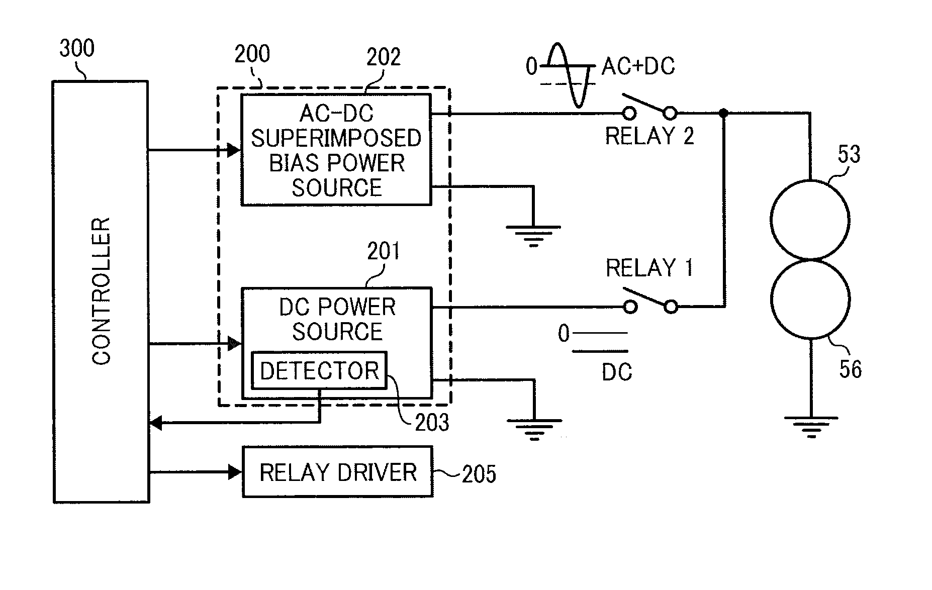
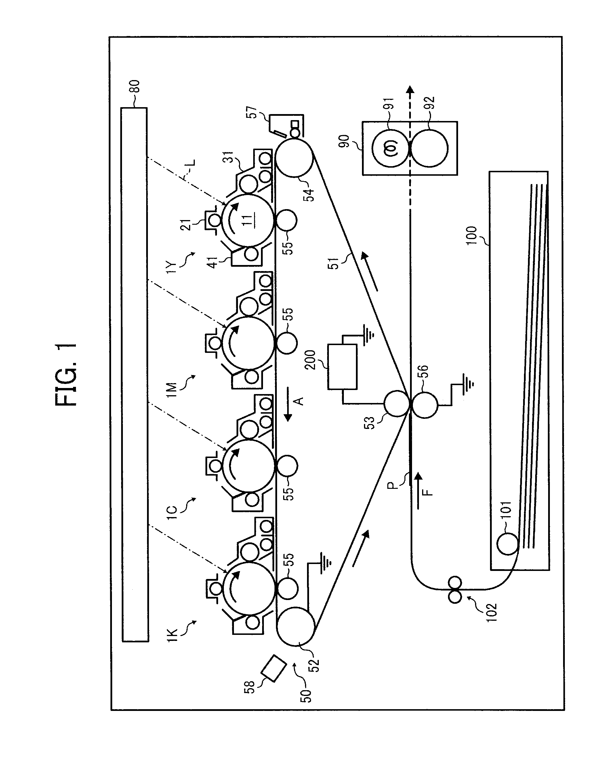
[0034]FIG. 20 is a table showing an effect of the eighth exam...

Problems solved by technology

However, toner does not transfer well to such embossed surfaces, in particular, the recessed portions of the surface.
This inadequate transfer of the toner appears as dropouts or white spots in the resulting output image.
Although advantageous and generally effective for its intended purpose, if the same amount of transfer bias correction is applied...

Method used


Image

  • Image forming apparatus
  • Image forming apparatus
  • Image forming apparatus

Examples


example 1

[0114]In a first example (EXAMPLE 1), for the AC component, an inclination of rising and falling of the voltage at a return direction side (toner returning from the recording medium to the belt side) is less than that of at a transfer direction side (toner transferring from the belt side to the recording medium). More specifically, a time A at the transfer direction side during which the voltage closer to the transfer direction side than from the center voltage value Voff is output, is longer than a return time B during which the voltage having a value closer to the polarity opposite to the transfer direction than from the center voltage value Voff is output. (A>B)

[0115]FIG. 7 shows a waveform chart of the EXAMPLE 1. According to the present illustrative embodiment, the return time is 40%, and the effect thereof is shown in FIG. 8.

[0116]In FIG. 8, when the peak-to-peak voltage Vpp is 12 kV and the time-averaged value Vave of the voltage is −5.4 kV, the center voltage value Voff is −...

example 2

[0117]In a second example (EXAMPLE 2), for the AC component, an inclination of rising and falling of the voltage at the return direction side is less than that of at the transfer direction side. More specifically, a transition time t1, during which the voltage shifts from the peak value of the voltage in the transfer direction to the center voltage value Voff, is shorter than a transition time t2, during which the voltage shifts from the center voltage value Voff to the peak value of the voltage having the polarity opposite that of the voltage in the transfer direction. (t2>t1)

[0118]FIG. 9 shows a waveform chart of the second example. According to the present illustrative embodiment, the return time is 40%, and the effect thereof is shown in FIG. 8. With this configuration, the time-averaged value Vave of the voltage can be closer to the transfer direction side than from the center voltage value Voff of the minimum and the maximum of the voltage.

example 3

[0119]In order to make an area at the return direction side smaller than an area at the transfer direction side relative to the center voltage value Voff of the AC component, in a third example (EXAMPLE 3), the return time B is shorter than the time A at the transfer side. With this configuration, the return time B is shorter than the time A at the transfer direction side.


PUM


Abstract

An image forming apparatus includes an image bearing member to bear a toner image on a surface thereof, a transfer device to transfer the toner image onto a recording medium, and a transfer bias power source to apply to the transfer device a superimposed transfer bias in which an alternating current (AC) component is superimposed on a direct current (DC) component in a superimposed transfer mode to transfer the toner image. The superimposed transfer bias has a waveform in which a first polarity in a direction of transferring the toner image onto the recording medium and a second polarity opposite the first polarity switch alternately. The superimposed transfer bias is output such that a standard value of each of the DC component and the AC component is multiplied by a respective correction ratio, and the correction ratio of the DC component is different from that of the AC component.

Description

CROSS-REFERENCE TO RELATED APPLICATIONS[0001]This patent application is based on and claims priority pursuant to 35 U.S.C. §119 to Japanese Patent Applications Nos. 2011-258702, filed on Nov. 28, 2011, 2012-087241, filed on Apr. 6, 2012, and 2012-179267 filed on Aug. 13, 2012 in the Japan Patent Office, which are hereby incorporated herein by reference in their entirety.BACKGROUND OF THE INVENTION[0002]1. Field of the Invention[0003]Exemplary aspects of the present invention generally relate to an electrophotographic image forming apparatus, such as a copier, a facsimile machine, a printer, or a multi-functional system including a combination thereof.[0004]2. Description of the Related Art[0005]Related-art image forming apparatuses, such as copiers, facsimile machines, printers, or multifunction printers having at least one of copying, printing, scanning, and facsimile capabilities, typically form an image on a recording medium according to image data. Thus, for example, a charger u...

Claims


Application Information

Patent Timeline
IPC IPC(8): G03G15/00G03G15/16
CPCG03G15/0189G03G15/1605G03G15/1675
Inventor SHIMIZU, YASUNOBUOGIYAMA, HIROMIISHII, HIROKAZUTANAKA, SHINYANAKAMURA, KEIGO
Owner RICOH KK
Why Eureka
Try Eureka