Tri-pole direct current transmission system topology structure based on modular multi-level converter (MMC)

A modular multi-level, DC power transmission system technology, applied in the field of power transmission and distribution, can solve problems such as power interruption of DC line transmission, threat to the safety and stability of the receiving end system, and disturbance of the AC system at both ends, so as to meet the needs of the DC line, Good engineering application value, the effect of stabilizing the AC system voltage

Active Publication Date: 2013-09-18
NR ELECTRIC CO LTD +1
View PDF6 Cites 48 Cited by
  • Summary
  • Abstract
  • Description
  • Claims
  • Application Information

AI Technical Summary

Problems solved by technology

[0008] figure 1 The three-pole direct current transmission scheme in the paper adopts the conventional LCC-HVDC technology, so it also has the disadvantages of LCC-HVDC
If the AC system on the inverter side fails, it will cause commutation failures at the three poles of the DC at the same time, resulting in the interruption of the transmission power of the DC line, which poses a threat to the safety and stability of the receiving end system.
In addition, during the operation of the three-pole DC system, the magnitude of the current in each pole and the voltage polarity and current direction of pole 3 need to change rapidly according to a certain period, which will inevitably cause disturbance to the AC system at both ends.

Method used


Image

  • Tri-pole direct current transmission system topology structure based on modular multi-level converter (MMC)
  • Tri-pole direct current transmission system topology structure based on modular multi-level converter (MMC)
  • Tri-pole direct current transmission system topology structure based on modular multi-level converter (MMC)

Examples


Embodiment Construction

[0024] The technical solution of the present invention will be described in detail below in conjunction with the accompanying drawings and specific embodiments.

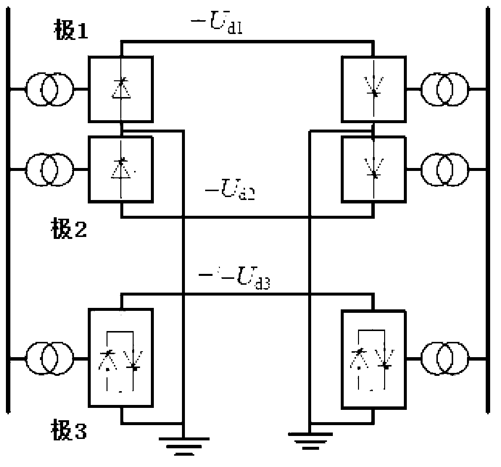
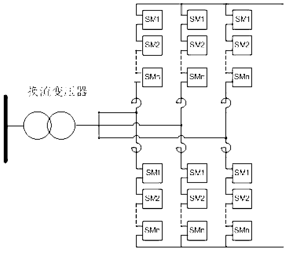
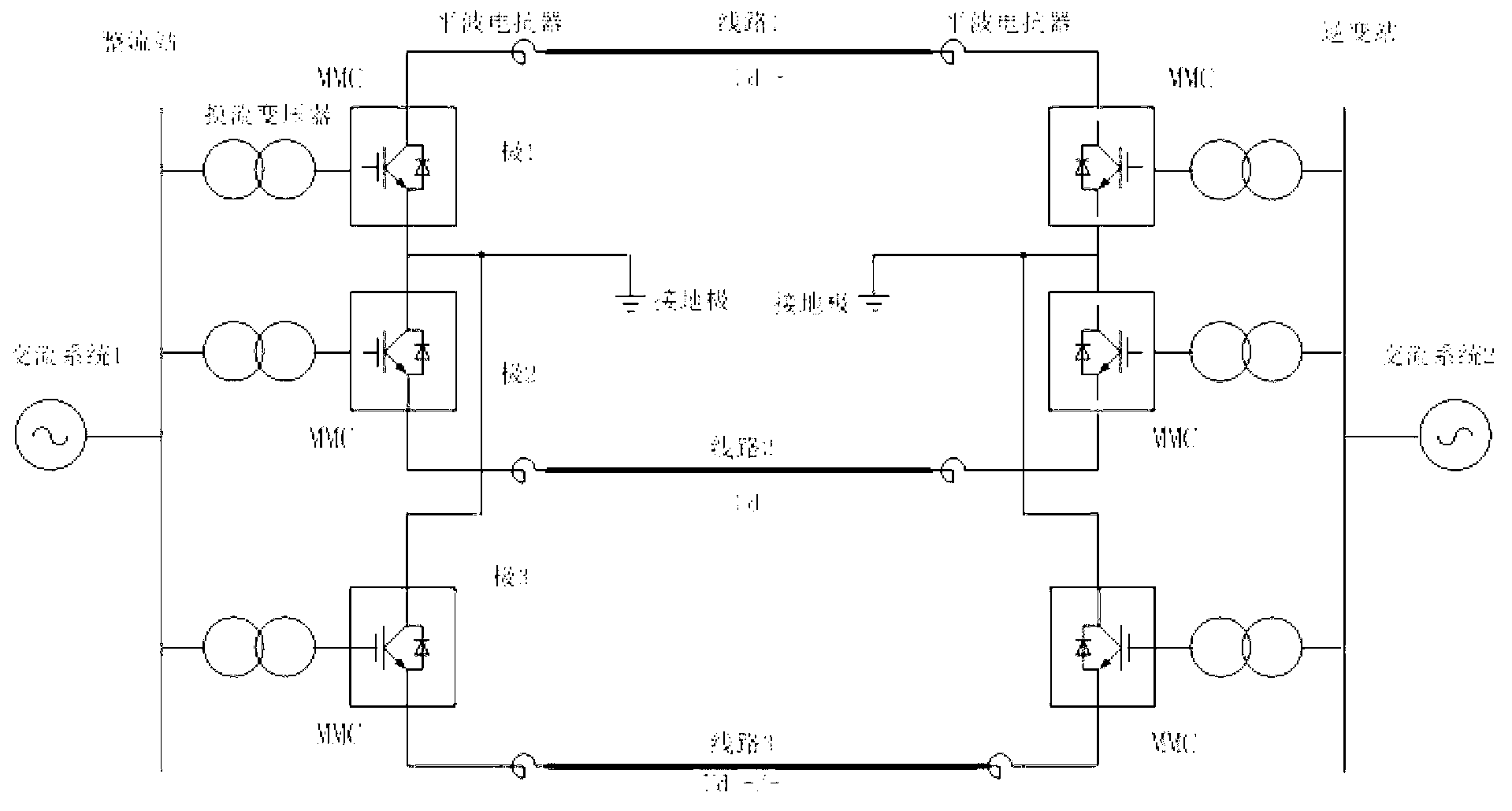
[0025] Such as Figure 1-3 As shown, the DC voltage polarities of each pole of the three-pole DC system are positive, negative, and positive / negative respectively, and the MMC is a modular multilevel converter; the present invention proposes a three-pole converter based on a modular multilevel converter Polar DC transmission system topology: including rectifier converter transformers, rectifier converters, rectifier smoothing reactors, DC overhead lines, inverter smoothing reactors, inverter converters and inverter converter transformers, rectifier converters and The inverter converters are respectively composed of a modular multilevel converter, and the three lines used can be cables or overhead lines. figure 2 Medium SM 1 -SM n All are modular multilevel converter sub-module units.

[0026] The rectifying and ...


PUM


Abstract

The invention discloses a tri-pole direct current transmission system topology structure based on an MMC. The tri-pole direct current transmission system topology structure is characterized in that direct current transmission is performed in a tri-pole connecting mode, and each pole comprises a rectification-side converter transformer, a rectification-side converter, a rectification-side smoothing reactor, a direct current transmission line, an inversion-side smoothing reactor, an inversion-side converter and an inversion-side converter transformer group. The rectification-side converters and the inversion-side converters are in modular multi-level structures, sub-modules of different amounts are connected in series and in parallel to be adapted to requirements for different voltage classes and currents, and three transmission lines used in a tri-pole direct current system are cables or overhead lines. The tri-pole direct current transmission system topology structure is high in reliability and capable of meeting the requirement for changing alternating current lines into direct current lines, phase change failures on the inversion side can be avoided under the condition that an alternating current system breaks down, voltages on two sides of the alternating current system can be stabilized, a alternating current filtering and reactive compensation device is not needed, and good application values are provided.

Description

technical field [0001] The invention relates to the technical field of power transmission and distribution, in particular to a three-pole direct current transmission system for transforming an existing alternating current line into a direct current transmission line. Background technique [0002] With the sustained and rapid development of my country's economy, the contradiction of power demand has become increasingly prominent. On the one hand, the growth of power load exceeds the transmission capacity of the original AC transmission line, and it is difficult to obtain a new transmission corridor due to land resources constraints; The maximum thermal power that the wire can withstand is less, so it is necessary to adopt new technology to further tap the power transmission potential of the existing line. [0003] Compared with AC transmission, with DC transmission, the line current can reach the maximum thermal limit that the wire can withstand. In 2004, Barthold LO propos...

Claims


Application Information

Patent Timeline
Patent Type & Authority Applications(China)
IPC IPC(8): H02J3/36
CPCY02E60/60
Inventor 胡铭邵震霞焦鑫艳黄志岭
Owner NR ELECTRIC CO LTD
Why Eureka
Try Eureka