Power factor correction type switching power supply unit

a power factor correction and power supply technology, applied in the emergency protective arrangements for limiting excess voltage/current, energy industry, and arrangements responsive to excess voltage, can solve the problems of abnormal voltage being applied to the load, inductor current isub>l /sub>may rise excessively, and direct current output voltage vout may rise, etc., to prevent the removal of too much instantaneous power, prevent squeaking, and stable direct current output voltage

Active Publication Date: 2011-05-26
FUJI ELECTRIC CO LTD
View PDF7 Cites 31 Cited by
  • Summary
  • Abstract
  • Description
  • Claims
  • Application Information

AI Technical Summary

Benefits of technology

[0022]According to the power factor correction type switching power supply unit of the aspect of the invention, it is possible to realize a transient response corrector circuit with a simple circuit, and it is possible to supply a stable direct current output voltage to a load, even when a transient response correction operati...

Problems solved by technology

However, as the improvement of the power factor is in a trade-off relationship with transient response characteristics with respect to a load fluctuation, or the like, there is a problem in a power supply unit used in a kind of application that requires transient response characteristics.
However, according to this method, as the voltage error signal Ver is increased while ignoring the response characteristics of the power factor correction type switching power supply unit, there is a problem in that the inductor current IL and the direct current output voltage Vout may rise excessively, and an abnormal voltage be applied to the lo...

Method used


Image

  • Power factor correction type switching power supply unit
  • Power factor correction type switching power supply unit
  • Power factor correction type switching power supply unit

Examples


first embodiment

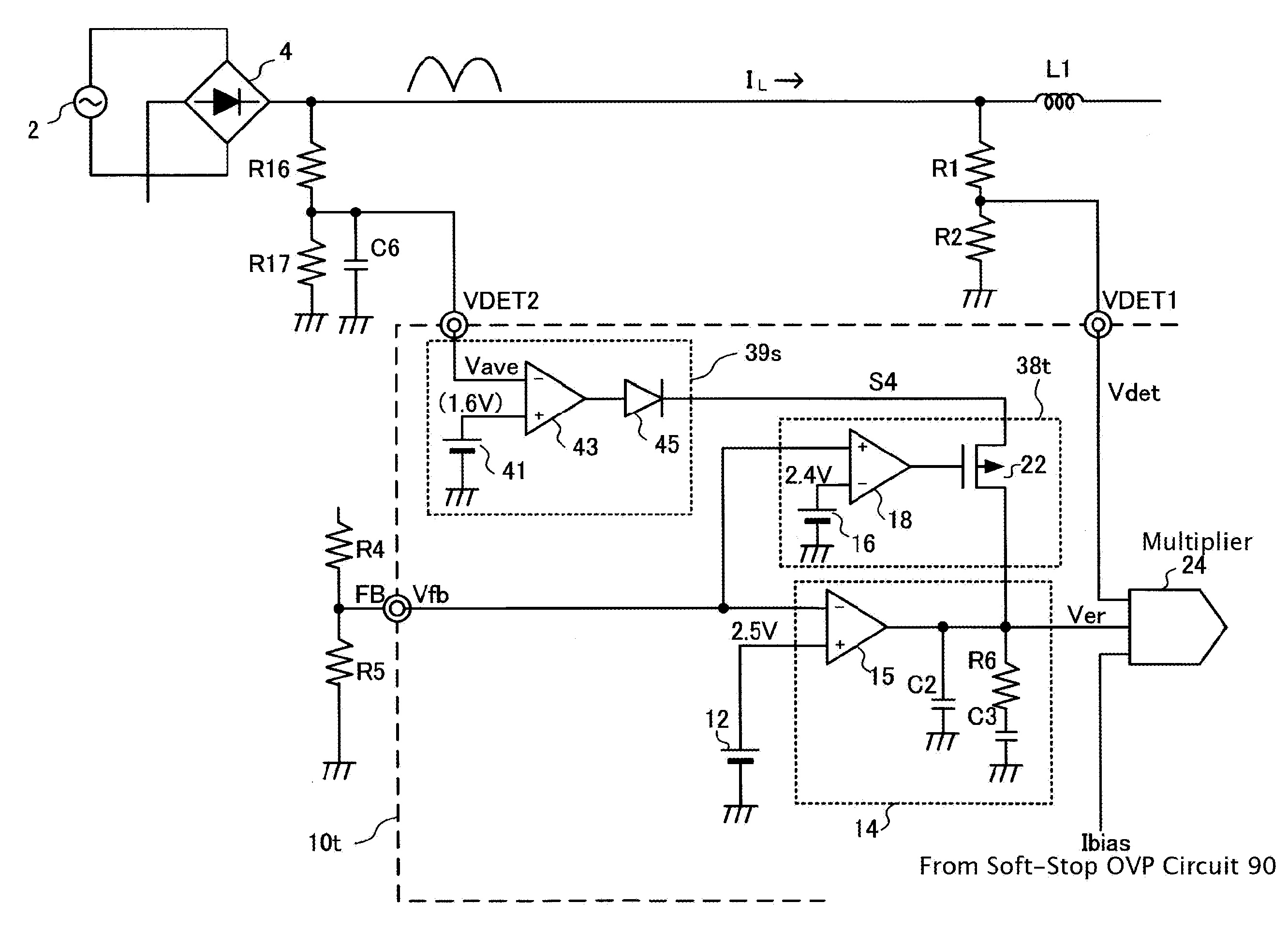
[0037]A power factor correction type switching power supply unit that operates in continuous mode, which is a first embodiment of the invention, has the same configuration as that of the heretofore known power factor correction type switching power supply unit shown in FIG. 12, except that the power factor correction control circuit 10 is replaced with a power factor correction control circuit 10s.

[0038]FIG. 1 is a circuit diagram showing the power factor correction control circuit according to the first embodiment of the invention. The power factor correction control circuit 10s is one that controls a current flowing to an alternating current commercial power supply 2 side into a sinusoidal wave in the same phase as that of an alternating current input voltage, while stabilizing a direct current output voltage Vout, in the same way as the power factor correction control circuit 10. A feedback voltage input terminal FB of the power factor correction control circuit 10s is connected...

second embodiment

[0109]Next, a description will be given of a power factor correction type switching power supply unit according to a second embodiment of the invention. FIG. 10 is a circuit diagram showing a configuration of a power factor correction control circuit according to the second embodiment of the invention. Here too, the configuration is the same as that of the heretofore known power factor correction type switching power supply unit shown in FIG. 12, except that the power factor correction control circuit 10 is replaced with a power factor correction control circuit 10t.

[0110]The power factor correction control circuit 10t is one that controls a current flowing to an alternating current commercial power supply 2 side into a sinusoidal wave in the same phase as that of an alternating current input voltage, while stabilizing a direct current output voltage Vout, and its feedback voltage input terminal FB is connected to one input terminal (the inversion input terminal) of an OTA 15. A re...

third embodiment

[0117]FIG. 11 is a circuit diagram showing a configuration of a power factor correction control circuit according to a third embodiment of the invention.

[0118]This power factor correction control circuit 10s is characterized in that it employs a voltage error amplifier circuit 14s using a voltage mode amplifier (an operational amplifier) 15a instead of the voltage error amplifier circuit 14 using the OTA 15. Regarding other configurations of the power factor correction control circuit 10s, reference numerals and characters corresponding to the first embodiment shown in FIG. 1 are given, and a description thereof will be omitted.

[0119]Herein, the voltage error signal Ver, which is the first input signal of the multiplier 24, is supplied via the resistor R18 from the output terminal of the voltage mode amplifier 15a to the multiplier 24. Also, the output terminal of the voltage mode amplifier 15a is connected to a terminal FB2. A phase compensation circuit formed of a resistor Ra and ...


PUM


Abstract

A soft-stop overvoltage protection circuit, into which a soft-stop overvoltage detection voltage proportional to a direct current output voltage is input, reduces the output of a multiplier in accordance with the soft-stop overvoltage detection voltage when the soft-stop overvoltage detection voltage exceeds a first threshold value. An overvoltage protection circuit, a second threshold value higher than the first threshold value being set, compulsorily turns off a switching element by outputting an overvoltage detection signal when the soft-stop overvoltage detection voltage exceeds the second threshold value. The soft-stop overvoltage protection circuit compulsorily increases the output of a voltage error amplifier circuit on the output voltage decreasing. When the output of the voltage error amplifier circuit increases suddenly, and the output voltage rises excessively, the soft-stop overvoltage protection circuit decreases the output of the multiplier, thus curbing the rise of the output voltage.

Description

BACKGROUND OF THE INVENTION[0001]1. Technical Field[0002]The present invention relates to a power factor correction type switching power supply unit that converts an alternating current voltage into a direct current voltage, and in particular relates to a power factor correction type switching power supply unit having a transient response correcting function that swiftly raises the output voltage when the output voltage decreases to or below a certain threshold value.[0003]2. Related Art[0004]In recent years, a switching power supply unit that has an alternating current voltage as an input has been widely utilized in electronic instruments. This kind of switching power supply unit is one which, by causing a switching operation of a switching element linking an input and an output, converts a full-wave rectified alternating current input voltage into a direct current output voltage of a desired size, and supplies it to a load.[0005]FIG. 12 is a circuit diagram showing one example of ...

Claims


Application Information

Patent Timeline
IPC IPC(8): H02M7/155
CPCH02M1/32Y02B70/126H02M1/4225Y02B70/10Y02P80/10
Inventor YABUZAKI, JUNCHEN, JIAN
Owner FUJI ELECTRIC CO LTD
Why Eureka
Try Eureka