
Wireless earphone

a wireless earphone and charging circuit technology, applied in the direction of electrical transducers, substation equipment, transportation and packaging, etc., can solve the problem of more expensive than simple charging circuits, the cost of charging ic 73/b> is more expensive, and achieve the effect of cheaper wireless earphones

Inactive Publication Date: 2005-07-07
MERRY ELECTRONICS CO LTD
View PDF4 Cites 32 Cited by
  • Summary
  • Abstract
  • Description
  • Claims
  • Application Information

AI Technical Summary

Benefits of technology

[0006] It is an object of the present invention to provide a cheaper wireless earphone.
[0007] Another object of the present invention is to provide a wireless earphone and adjust the charging current correctly by a feedback function. By this way, the voltage of the rechargeable battery is steadier.
[0010] To achieve above-mentioned objects, the present invention provides a charging circuit for receiving the control signals output from the microprocessor and charging a rechargeable battery. The charging circuit comprises: a charging current control circuit receiving input direct current and control signals, a first detecting circuit detecting the charging current of the charging current control circuit, and a second detecting circuit detecting the voltage value of the rechargeable battery. The charging current control circuit also outputs charging current and changes the current values according to the control signals. The microprocessor may detect the voltage value of the rechargeable battery by the second detecting circuit and the current value of the rechargeable battery by the first detecting circuit. Hence, the microprocessor can change the charging current and charge the rechargeable battery.

Problems solved by technology

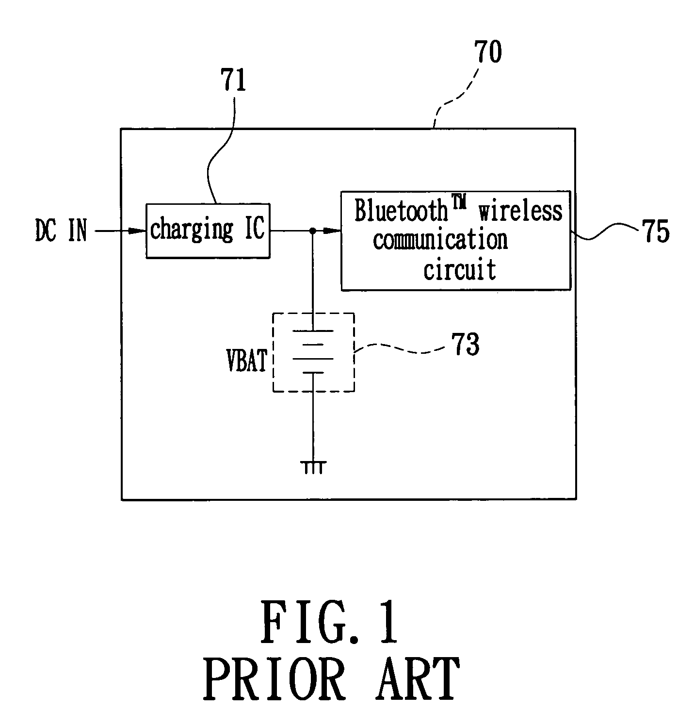
The cost of using the charging IC 73 is more expensive than using simple charging circuit.

Method used


Image

  • Wireless earphone
  • Wireless earphone
  • Wireless earphone

Examples


Embodiment Construction

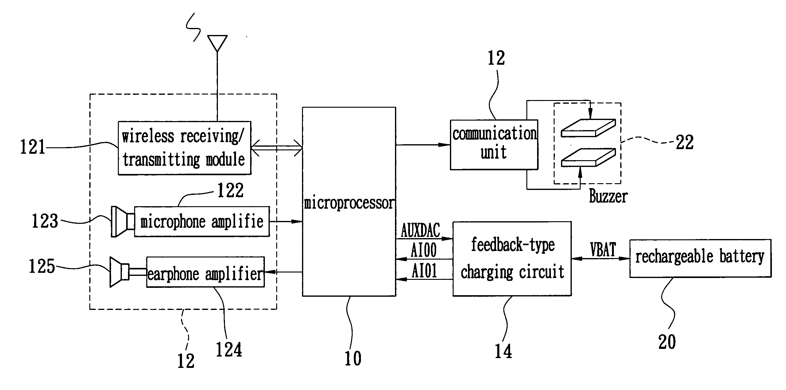
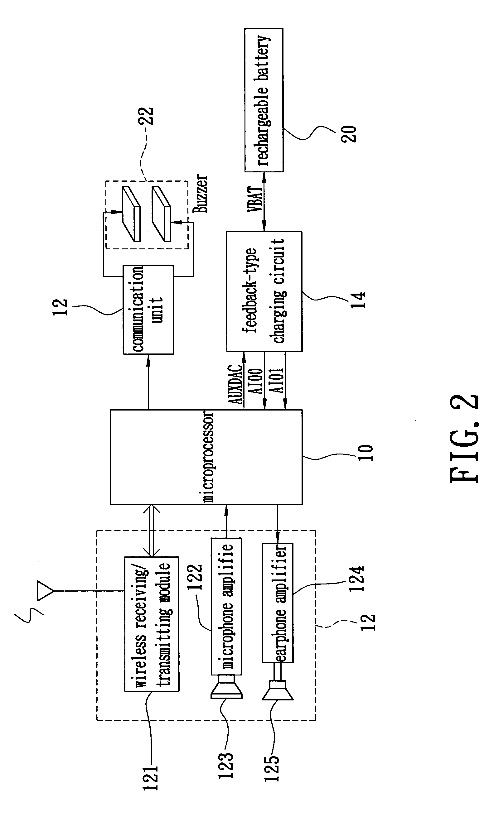
[0019] Reference is made to FIG. 2, which shows a system block diagram of the present invention. An internal structure of a wireless earphone in the present invention comprises a microprocessor 10, a communication unit 12, a feedback-type charging circuit 14, a rechargeable battery 20, a buzzer control circuit 16 and a buzzer 22.

[0020] The communication unit 12 can communicate with mobile phones by transferring wireless signals; the communication unit 12 has the same internal structure with prior art wireless earphones, which transfers wireless signals by a wireless receiving / transmitting module 121. Therefore, a microphone 123 can receive audio signals, and the audio signals will be processed by a microphone amplifier 122. After that, the wireless receiving / transmitting module will transmit the audio signals transferred by the microprocessor 10. The microprocessor 10 may also decode the wireless signals received by the wireless receiving / transmitting module 121 into audio signals;...


PUM


Abstract

A wireless earphone communicates with a mobile phone by wireless and comprises a microprocessor, a feedback-type charging circuit and a rechargeable battery therein. The microprocessor output control signals to control the feedback-type charging circuit for charging the rechargeable battery; the feedback-type charging circuit also feeds back the charging current and charging states of the rechargeable battery to the microprocessor. Therefore, the microprocessor may change the charging current depending on the states of the rechargeable battery. By changing the voltage of the control signals, the charging current of the feedback-type charging circuit can be adjusted by the microprocessor. The present invention provides a charging design by software control to reduce the production cost of wireless earphone.

Description

BACKGROUND OF THE INVENTION [0001] 1. Field of the Invention [0002] The present invention is a wireless earphone, especially relates to a wireless earphone that can charge rechargeable batteries with an interior charging circuit. [0003] 2. Description of Related Art [0004] Wireless earphones used with mobile telephones mainly use the Bluetooth™ wireless communication technique. Therefore, the above-mentioned earphone is also referred to a Bluetooth™ earphone. Rechargeable batteries are used as power sources for prior art Bluetooth™ earphones, and the rechargeable batteries are usually set inside the Bluetooth™ earphones. FIG. 1 shows a schematic structure diagram of the Bluetooth T earphone 70. A rechargeable battery 73 is charged by supplying a direct current to an input terminal of a charging IC 71, and the charging IC 71 will provide the electricity for the rechargeable battery 73. After the rechargeable battery 73 is charged, it will provide electric power for a Bluetooth T wire...

Claims


Application Information

Patent Timeline
Patent Type & Authority Applications(United States)
IPC IPC(8): H02J7/00H02J7/04H02J7/06H02J7/24H04M1/60H04R1/00
CPCH04M1/6041H02J7/0072H02J7/00714H02J7/007182
Inventor LIN, YEN HSI
Owner MERRY ELECTRONICS CO LTD
Learn More