Novel thyristor converter valve module

一种晶闸管换流阀、阀模块的技术,应用在输出功率的转换装置、电力传输交流网络、变换设备结构零部件等方向,能够解决更新换代缓慢、阀模块重量增大、阀模块内部空间浪费等问题,达到降低应力集中程度、分散承重载荷、减小几何尺寸的效果

Active Publication Date: 2010-06-02
CHINA ELECTRIC POWER RES INST
View PDF0 Cites 51 Cited by
  • Summary
  • Abstract
  • Description
  • Claims
  • Application Information

AI Technical Summary

Problems solved by technology

The metal frame type valve module has high structural support strength, but the requirements for electrical insulation must be considered under high voltage, which will increase the structural size of the valve module frame, waste the internal space of the valve module, and increase the weight of the valve module. Big
The combined frame valve module has the problem of mechanical strength. Because the valve module frame has to bear a large weight load, the structural strength of the insulating channel beam, such as tensile strength, bending strength and shear strength, is very high. Increase the difficulty and manufacturing cost of the valve module design, which is not conducive to the engineering application of the converter valve
In the modular decentralized valve module structure, the thyristors, damping resistors, damping capacitors, gate units and saturated reactors inside the valve module are assembled in a modular manner. This structure design has a number of dispersed sub-modules inside the valve module. Too many, resulting in the difficulty of on-site assembly of the valve module project, and it is not conducive to the improvement of the installation efficiency of the valve module. At the same time, this modular decentralized structure requires high precision on-site installation. The operating skills of the technicians who install the modules are highly demanded
[0005] The component selection and replacement of the current converter valves in operation is slow, the latest technology of the current components is not applied, and it cannot meet the needs of the current DC transmission boost and capacity increase

Method used


Image

  • Novel thyristor converter valve module
  • Novel thyristor converter valve module
  • Novel thyristor converter valve module

Examples


Embodiment Construction

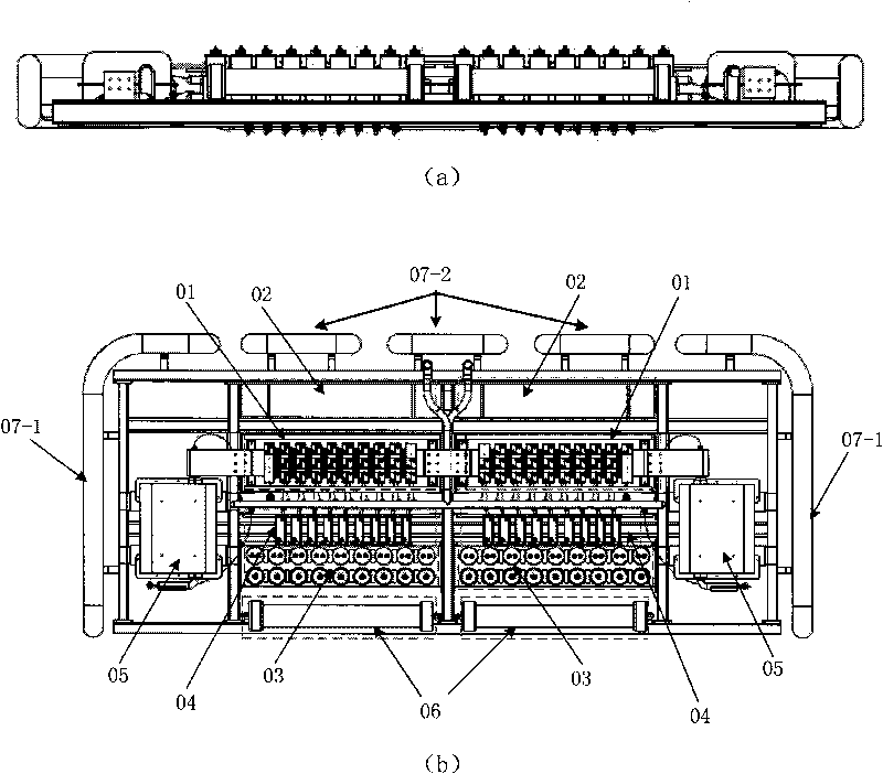
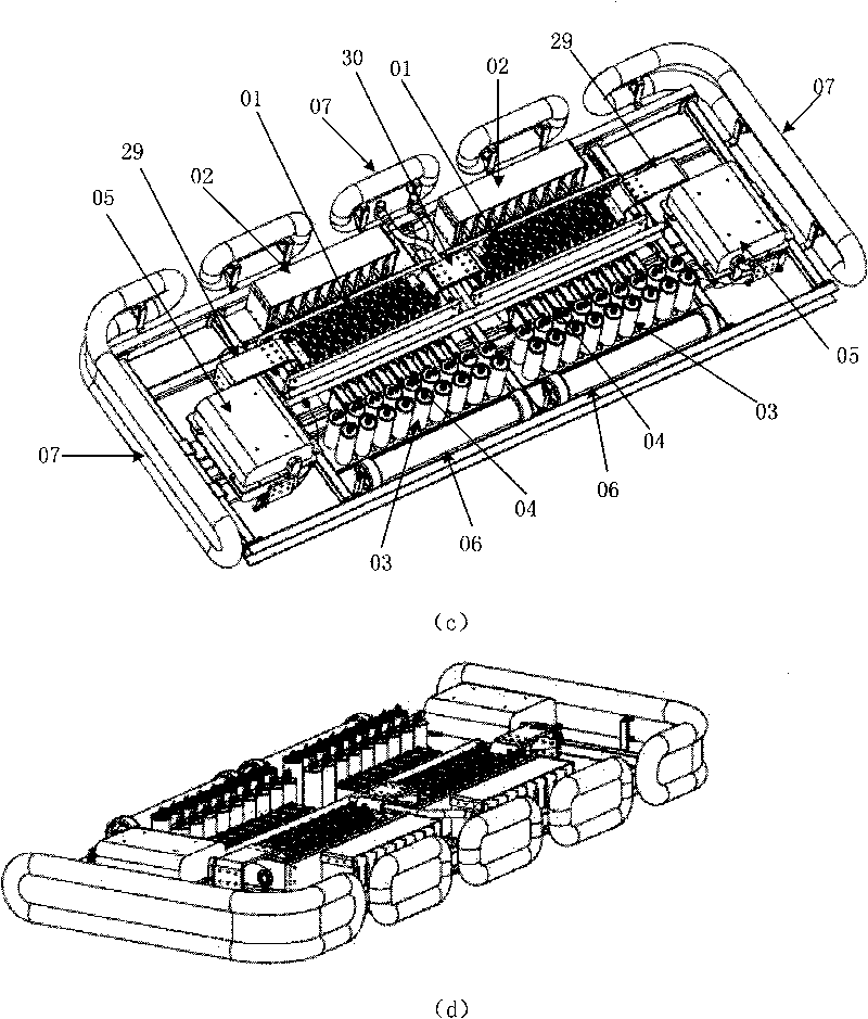
[0032]For a thyristor-level component, the gate unit 02, the damping resistance unit 04 and the damping capacitor unit 03 are respectively located on both sides of the thyristor unit 01. In terms of structural design, the deviation between the center of gravity and the geometric center of the thyristor-level component is not too large, which is conducive to improving The stress condition of the valve frame. For a valve section, the heaviest saturable reactor assembly 05 and thyristor unit 01 are arranged on the same axis of the valve section, and its center of gravity is close to the geometric center of the valve section structure, thereby improving the force condition of the entire valve section. For a thyristor stage, the damping capacitor unit 03 is placed next to the damping resistor unit 04, which shortens the distance between the terminal of the damping capacitor 03 and other electrical connection components, shortens the electrical wiring length of the thyristor stage, a...


PUM


Abstract

The invention provides electronic equipment with high voltage and high power, which is used for converting alternating current (AC) voltage into direct current (DC) voltage or converting DC voltage into AC voltage, in particular a thyristor converter valve module. A whole valve module is divided into two same segments, and each segment comprises a saturable reactor, a thyristor, a DC equalizing resistor unit, an energy-extracting resistor unit, a damping resistor unit, a damping capacitor unit, a gate electrode unit and a water cooling system, wherein the reactors of the electronic equipment are connected in series to meet the requirements on different transmission powers and different power voltage grades. The equipment is core equipment for high-voltage DC power transmission and can be applied to a DC-AC converting system, meet the requirements of different voltage grades and for the DC converting system with different voltage grades, including the super high voltage of 800 kV or above.

Description

technical field [0001] The invention relates to the field of high-power electric power electronic converter valves in electric power systems, in particular to a thyristor converter valve module for high-voltage direct current transmission. Background technique [0002] As the core component of the HVDC transmission system, the converter valve has been developed and applied for many years. The converter valve module of traditional HVDC power transmission is based on the thyristor series structure as the core, and at the same time includes the control, trigger and protection system of the thyristor. Focusing on the safe and reliable operation of the thyristor, the converter valve module includes the following auxiliary components: saturable reactor, thyristor unit, damping resistor unit, damping capacitor unit, DC voltage equalizing resistor, energy-taking resistor, used for thyristor control, triggering and protection The control unit, and the water cooling system to meet th...

Claims


Application Information

Patent Timeline
Patent Type & Authority Applications(China)
IPC IPC(8): H02M1/00H01L25/00
CPCY02E60/60H02J3/36H01L2924/0002H01L25/16H01L25/112H01L25/117H02M7/003Y10T137/6552H01L2924/00
Inventor 魏晓光汤广福温家良张升
Owner CHINA ELECTRIC POWER RES INST
Why Eureka
Try Eureka