Drive control apparatus for vehicle

a technology for controlling apparatus and vehicles, which is applied in mechanical apparatus, driver input parameters, transportation and packaging, etc., can solve the problems the possibility of achieve the effect of suppressing giving an uncomfortable feeling to the driver, and reducing the amount of drive for

Active Publication Date: 2013-06-06
TOYOTA JIDOSHA KK
View PDF1 Cites 6 Cited by
  • Summary
  • Abstract
  • Description
  • Claims
  • Application Information

AI Technical Summary

Benefits of technology

[0008]The invention provides a drive control apparatus for a vehicle that makes it possible to suppress giving an uncomfortable feeling to a driver when the shift position is switched from a non-driving position to a driving position while the accelerator is in an on state.
[0010]According to this configuration, the control unit executes a drive force restriction process of reducing the drive force output from the prime mover when the shift position is switched from a non-driving position to a driving position while the accelerator is in an on state. Here, examples of circumstances where the shift position is switched from a non-driving position to a driving position while the accelerator is in an on state are: circumstances where the driver unintentionally operates the accelerator to an on state before switching the shift position, such as when the driver intends to start the vehicle hurriedly from a stationary state. In such circumstances, if the drive force of the prime mover is transmitted to the wheels when the shift position is switched from a non-driving position to a driving position while the accelerator is in an on state, there is a possibility of giving an uncomfortable feeling to the driver. In this respect, according to the configuration described above, the drive force restriction process described above is executed under such circumstances, thereby reducing the drive force output from the prime mover, and therefore the start of the vehicle is made moderate, and it is made possible to suppress giving an uncomfortable feeling to the driver.
[0012]Here, when the shift position is switched from the neutral position to a driving position while the accelerator is in an on state, if the operation of the accelerator to an on state is an operation of starting the vehicle from a temporary stationary state, for example, the continuation time of the neutral position, during which the shift position is in the neutral position, immediately before the shift position is switched to the driving position (hereinafter, referred to as the continuation time of the neutral position) is long. On the other hand, if the operation of the accelerator to an on state is an operation of starting the vehicle to get the vehicle out of a muddy road, the shift position is rapidly switched between the drive position and the reverse position, which are the driving positions, in order to move the vehicle backwards and forwards. Therefore, the continuation time of the neutral position is shorter than that in the case of an operation of starting the vehicle from a temporary stationary state as described above. In this way, the circumstances of the vehicle, in which a start operation has been performed, can be determined from the continuation time of the neutral position. According to the configuration described above, the mode of reducing the drive force in the drive force restriction process changes in accordance with the continuation time of the neutral position, and therefore the reduction amount of the drive force, and the like, is adjusted in accordance with the circumstances of the vehicle. Therefore, the occurrence of excess or deficiency in the mode of reducing drive force is prevented in the drive force restriction process, and it is possible to suppress giving an uncomfortable feeling to the driver.
[0013]Consequently, it is possible to reliably suppress giving an uncomfortable feeling to the driver when the shift position is switched from a non-driving position to a driving position with the accelerator being in an on state.

Problems solved by technology

In such circumstances, if the drive force of the prime mover is transmitted to the wheels when the shift position is switched from a non-driving position to a driving position while the accelerator is in an on state, there is a possibility of giving an uncomfortable feeling to the driver.
Therefore, if the mode of reducing the drive force in the drive force restriction process is made universal regardless of the circumstances of the vehicle, excess or deficiency may occur in the mode of reducing the drive force in the drive force restriction process, depending on the circumstances of the vehicle, and this may give an uncomfortable feeling to the driver.

Method used


Image

  • Drive control apparatus for vehicle
  • Drive control apparatus for vehicle
  • Drive control apparatus for vehicle

Examples


Embodiment Construction

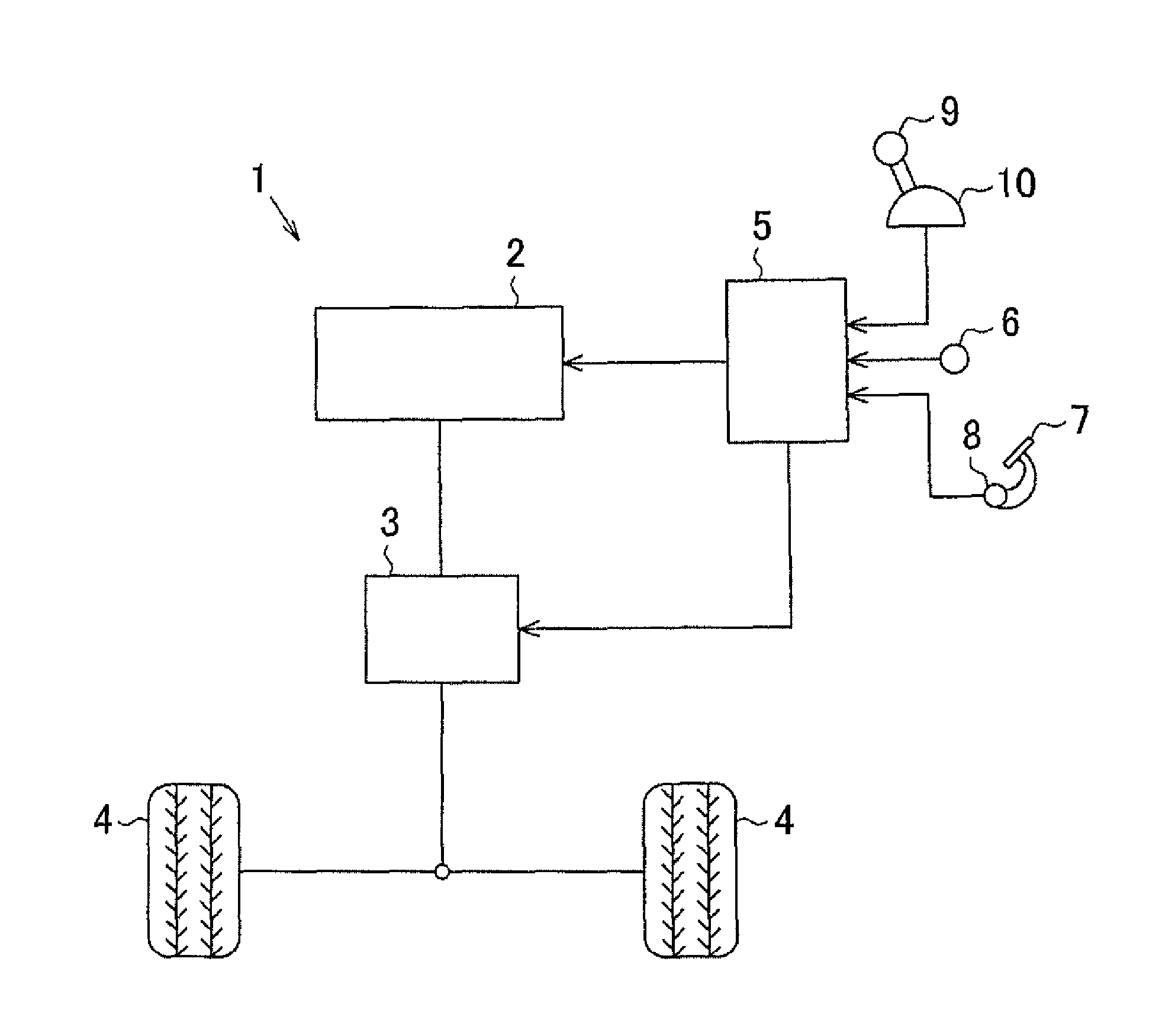
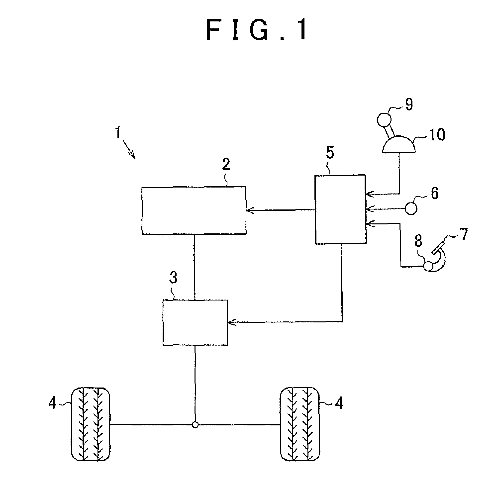
[0021]An embodiment of a drive control apparatus for a vehicle according to the invention will be described below with reference to FIGS. 1 to 6. As shown in FIG. 1, an internal combustion engine 2, which is a drive power source, and a transmission 3 that transmits drive force output from the internal combustion engine 2 to vehicle wheels 4, are mounted on a vehicle 1.

[0022]In addition, an electronic control apparatus 5 that executes various control procedures relating to the internal combustion engine 2 and the transmission 3 is mounted on the vehicle 1. The electronic control apparatus 5 includes a central processing unit (CPU) that carries out calculation processing relating to the various control procedures, a read-only memory (ROM), in which programs and data for the various control procedures are stored, a random-access memory (RAM) that temporarily stores the results of calculation processing, and the like. The electronic control apparatus 5 reads in detection signals from va...


PUM


Abstract

A drive control apparatus for a vehicle includes: a control unit that controls drive force output from an engine in accordance with operation of an accelerator pedal; and a shift mechanism capable of selectively switching a shift position to a driving position or a non-driving position. The shift mechanism transmits the drive force to wheels when the shift position is in the driving position, and interrupts transmission of the drive force when the shift position is in the non-driving position. The control unit executes a drive force restriction process of reducing the drive force when the shift position is switched from the non-driving position to the driving position while the accelerator pedal is in an on state, and, when the switching is from a neutral position, the control unit changes a mode of reducing the drive force in accordance with a continuation time of the neutral position.

Description

INCORPORATION BY REFERENCE[0001]The disclosure of Japanese Patent Application No. 2011-264984 filed on Dec. 2, 2011 including the specification, drawings and abstract is incorporated herein by reference in its entirety.BACKGROUND OF THE INVENTION[0002]1. Field of the Invention[0003]The invention relates to a drive control apparatus for a vehicle that controls drive force output from a prime mover serving as a drive power source of a vehicle, in accordance with operation of an accelerator.[0004]2. Description of Related Art[0005]As described in Japanese Patent Application Publication No. 61-190135 (JP 61-190135 A), a vehicle, such as an automobile, has a control unit that controls drive force output from a prime mover in accordance with operation of an accelerator by a driver, and the drive force output from the prime mover is transmitted to wheels of the vehicle, whereby the vehicle runs. Furthermore, the vehicle is also provided with a shift mechanism that enables the driver to sel...

Claims


Application Information

Patent Timeline
Patent Type & Authority Applications(United States)
IPC IPC(8): B60W10/04
CPCB60W10/04B60W10/06B60W10/115B60W30/1846B60W2510/0604B60W2510/101Y10T477/677B60W2520/10B60W2540/16B60W2710/0666F16H2061/0488F16H2063/508B60W2520/04
Inventor KODAMA, SHINYAOHBAYASHI, MOTONARIMINASE, YUKITAKAGI, MASASHITAKAGI, TOSHIHIRO
Owner TOYOTA JIDOSHA KK
Why Eureka
Try Eureka