Bistable electromagnetic actuating device and camshaft actuating device

a technology of electromagnetic actuation and camshaft, which is applied in the direction of electrical equipment, basic electric elements, and electromagnetic actuation devices, can solve the problems of mechanical stability being endangered at even faster switching speeds, weld seams with which the pole discs associated with the permanent magnet means are fastened to the actuating element are also subject to high stresses, and achieves good mechanical stability. , the effect of absorbing large forces

Inactive Publication Date: 2013-06-13
ETO MAGNETIC GMBH
View PDF16 Cites 10 Cited by
  • Summary
  • Abstract
  • Description
  • Claims
  • Application Information

AI Technical Summary

Benefits of technology

[0014]With respect to the actual design of damping elements of the damping means, there are different possibilities. For instance, it is possible and advantageous to provide what are known as topographic springs, in particular ring-shaped ones, in particular in a wave shape, which can produce a counter-force which damps the impact at a very short distance. It is also possible to provide damping elements in the form of plate springs, which can produce and absorb large forces at an extremely small distance. At least one damping element, in particular a plate spring, is preferably designed in such a manner that it absorbs as much kinetic energy as possible at the start of a force effect and collapses after a certain point and then effects hardly any counter-forces. This design has the advantage that the spring force is low in the first and / or second switch position and thus the retaining force produced by the permanent magnet means is maximal. Conversely, a damping element designed in such a manner has the advantage that it has an accelerating (assisting) effect from a certain stroke and thus has a positive influence on the switching dynamics. In order to have as little influence as possible on the magnetic field, a damping element comprising or consisting of beryllium and / or at least one beryllium alloy could for example be used.
[0015]It is also possible to use a diaphragm spring as at least one damping element. The use of plate or diaphragm springs makes it possible and preferred to maintain a spring characteristic which behaves initially progressively over the stroke region and only behaves degressively in the last part of the stroke.
[0016]The provision of elastomer material elements means that the system can be made “softer”, in particular in combination with a further, preferably metallic spring element. The delay path can be selected / designed in such a manner that the accelerations are precisely the right magnitude for connection points such as weld seams to withstand the stresses safely throughout the service life.

Problems solved by technology

The known bistable electromagnetic actuating devices have proven effective, but problems have arisen in the design.
As permanent magnet means are generally comparatively brittle, the mechanical stability can be endangered at even faster switching speeds.
The weld seams with which the pole discs associated with the permanent magnet means are fastened to the actuating element are also subject to high stresses.

Method used


Image

  • Bistable electromagnetic actuating device and camshaft actuating device
  • Bistable electromagnetic actuating device and camshaft actuating device
  • Bistable electromagnetic actuating device and camshaft actuating device

Examples


Embodiment Construction

[0025]In the figures, identical elements and elements having identical functions are provided with the same reference symbols.

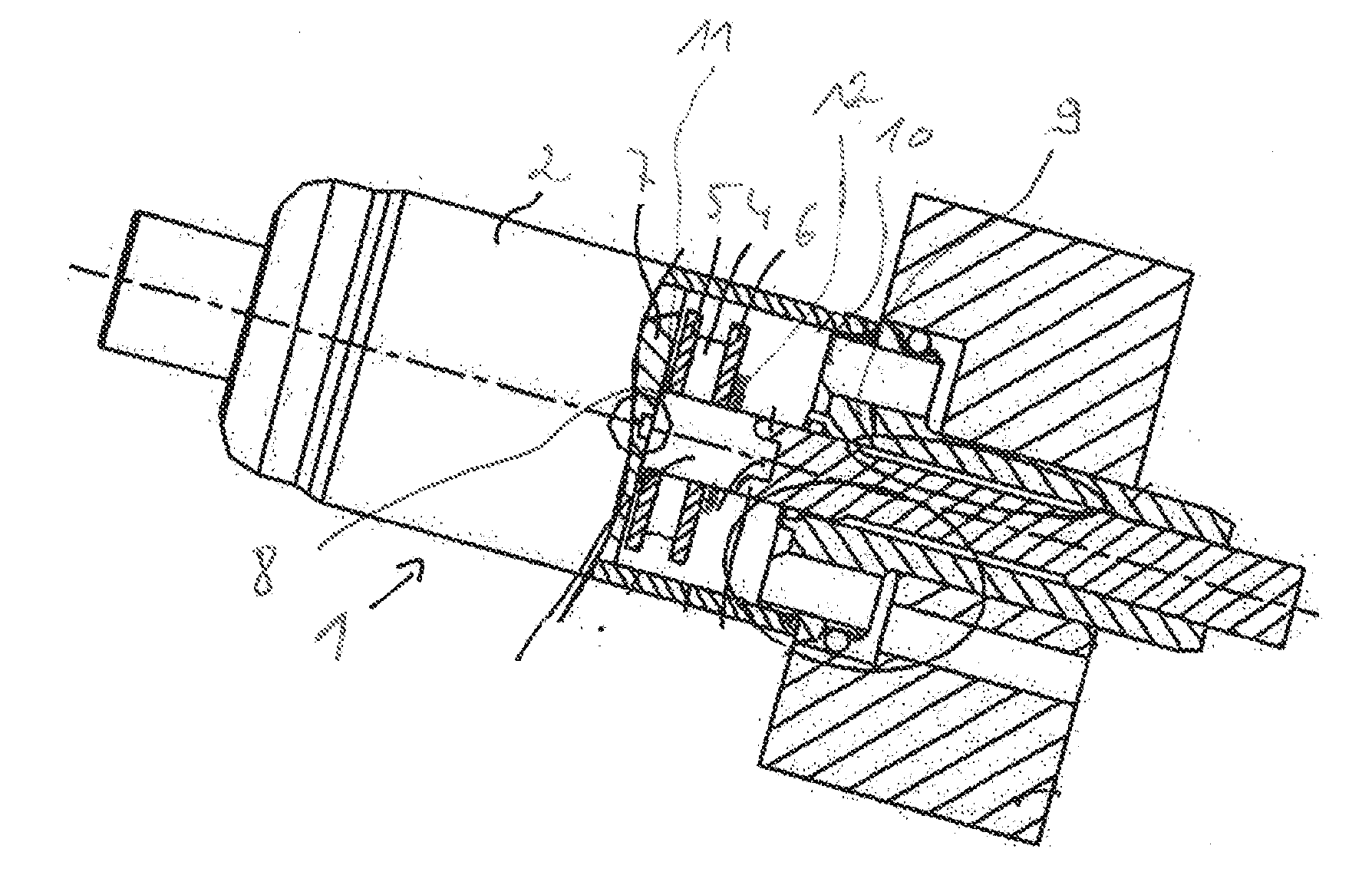
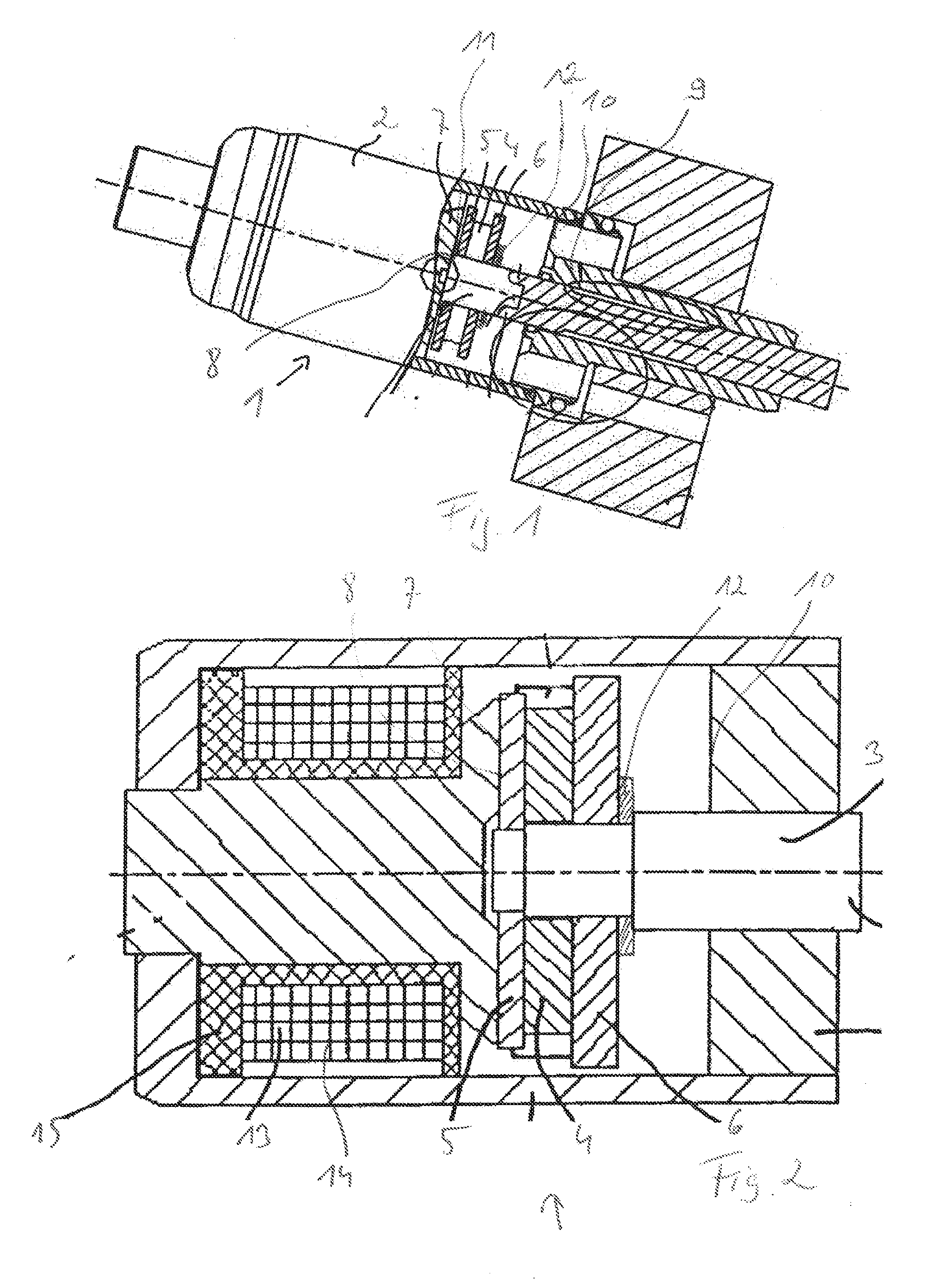
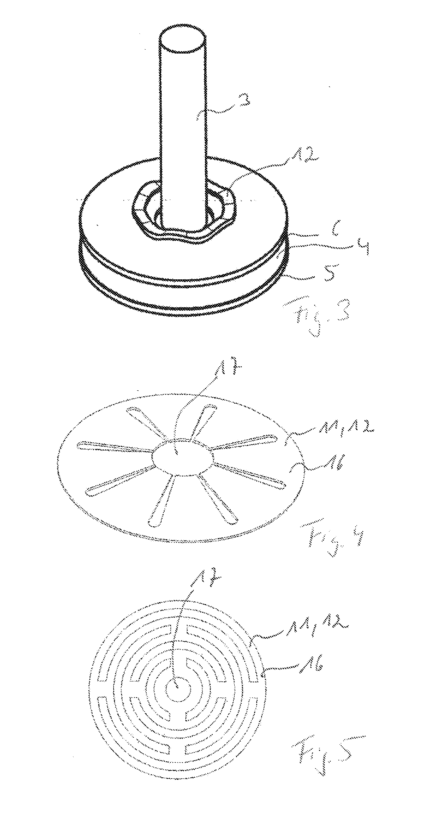
[0026]FIG. 1 shows a bistable electromagnetic actuating device 1, which interacts in an actuating manner with an actuating partner (not shown), in particular a camshaft stroke switching system. The actuating device 1 comprises a hollow-cylindrical, magnetically conductive bushing element 2, inside which an elongated, piston-shaped actuating element 3 is arranged. The actuating element 3 penetrates disc-shaped permanent magnet means 4, which are arranged between a first and a second magnetically conductive pole disc5, 6. The pole discs 5, 6 are welded to the piston-shaped actuating element 3. In the actual exemplary embodiment, the pole discs 5, 6 have a larger radial extent but a smaller thickness extent than the permanent magnet means 4. The actuating element 3 can be moved between a stationary core region 7, which forms a first stop face 8, and a sleeve-sha...


PUM

PropertyMeasurementUnit
magnetically conductiveaaaaaaaaaa
displacementaaaaaaaaaa
dampingaaaaaaaaaa

Abstract

A bistable electromagnetic actuating device and a camshaft actuating device for displacing a camshaft in a motor vehicle having an electromagnetic actuating device.

Description

BACKGROUND OF THE INVENTION[0001]The invention relates to a bistable electromagnetic actuating device and a camshaft actuating device for displacing a camshaft in a motor vehicle having an electromagnetic actuating device.[0002]Such generic actuating devices are known and described for example in DE 10 240 774 B4 or DE 20 2006 011 905 U1. In contrast to conventional actuating devices, the above electromagnetic actuating devices do not have a restoring spring, so the actuating-element-side permanent magnet means with the actuating element does not have to be accelerated counter to the force of such a restoring spring. Substantially improved switching times and improved switching dynamics result from this. The disc-shaped permanent magnet means are used to hold the actuating element securely in the housing in a (retracted) rest state by interaction with the core region. The actuating-element-side permanent magnet means also have a repulsion effect when the coil device is excited to pr...

Claims


Application Information

Patent Timeline
Patent Type & Authority Applications(United States)
IPC IPC(8): F01L1/46H01F7/08
CPCF01L2001/0473F01L2013/0052F01L2820/031H01F7/1646H01F7/08F01L13/0036F01L2810/03F01L1/46
Inventor SCHIEPP, THOMASBUERSSNER, JOERG
Owner ETO MAGNETIC GMBH
Why Eureka
Try Eureka