Press

a press and guiding unit technology, applied in the field of presses, can solve the problems of defective pressing results, deformation of press components, and considerable additional expense of tool guiding units, and achieve the effect of high motor weigh

Active Publication Date: 2014-09-25
MASCHFAB LAUFFER
View PDF1 Cites 4 Cited by
  • Summary
  • Abstract
  • Description
  • Claims
  • Application Information

AI Technical Summary

Benefits of technology

[0012]According to a further development, the upper transfer element may comprise an upper transfer bridge and/or the lower transfer element may comprise a lower transfer bridge. It is then furthermore possible that two upper drive units are provided, which are fastened to the upper transfer bridge, and/or that two lower drive units are provided, which are fastened to the lower transfer bridge. By providing two drive units per press axis, the dimensions of the respective drive units can be smaller. The two drive units, which are assigned to one axis of the press, can be operated in opposite directions with the objective that the reaction torques which are generated by the two driving moments of the drives, compensate one another and, accordingly, do not bring about any deformations in the arrangement, which takes up the drives. An effect, which is compensatory in this respect, is achieved if the threaded spindles of the oppositely operated drives have opposite lead angles (right-handed and left-handed threads). Furthermore, an upper force transfer element may be disposed between the upper transfer bridge and the upper p

Problems solved by technology

As a result, the manufacturing tolerances add up and, because of the high forces of the press, components of the press may become deformed.
Consequently, the pressing result may be defective.
However, this leads to a considerable additional expense with regard to the tool guiding units.
In addition, during the pressing, there is increased wear of individual components, such as seals and

Method used


Image

  • Press
  • Press

Examples


Embodiment Construction

[0020]While this invention may be embodied in many different forms, there are described in detail herein a specific preferred embodiment of the invention. This description is an exemplification of the principles of the invention and is not intended to limit the invention to the particular embodiment illustrated.

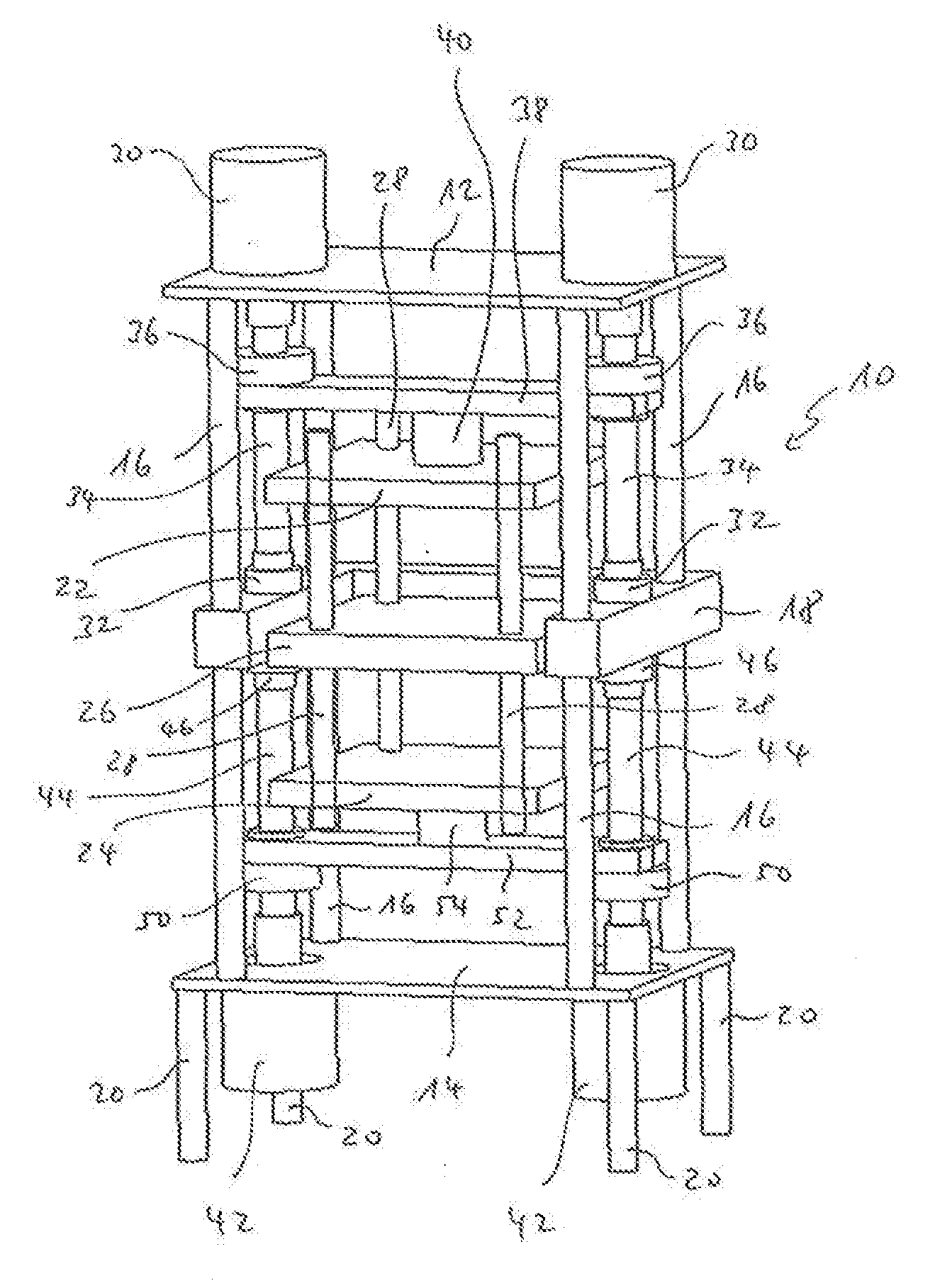
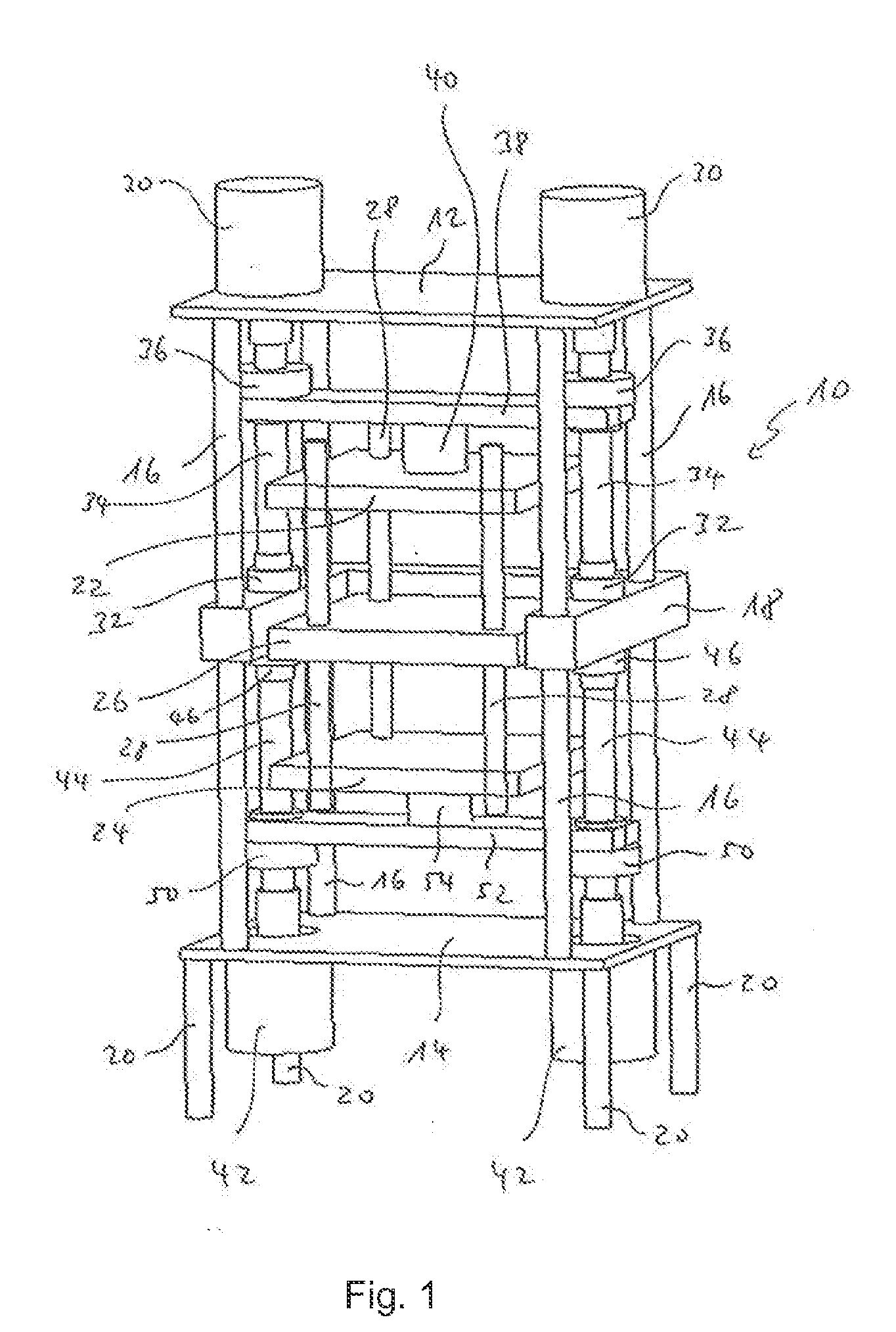
[0021]An example of the invention is explained in greater detail in the following by means of a drawing. The single FIGURE diagrammatically shows an inventive press in a perspective view. The inventive press has a press frame 10 with an upper retaining plate 12 and a lower retaining plate 14. In the example shown, the upper and the lower retaining plates 12, 14 are connected with one another over four spacers 16, which extend in the vertical direction and with a supporting element 18, which is disposed approximately centrally between the upper and lower retaining plates 12, 14. In the example shown, the supporting element 18 is constructed in one piece and has a U-shaped prof...


PUM

PropertyMeasurementUnit
Distanceaaaaaaaaaa

Abstract

A press for producing a pellet from powdered material, comprising a press frame with an upper and a lower retaining plate, which are connected to one another by several vertical spacers and with at least one supporting element, which is disposed between the upper and the lower retaining plate, a tool guiding unit with at least one upper punch unit with at least one upper press punch and/or at least one lower punch unit with at least one lower press punch and with a die assembly with at least one holder for powdered material, which is to be pressed by the upper and/or lower press punch, wherein the tool guiding unit is disposed at the supporting element, and at least one upper drive unit for moving the upper punch unit in the vertical direction and/or at least one lower drive unit for moving the lower punch unit and or the die assembly in the vertical direction, wherein, when the press is operating, the upper drive unit and/or the lower drive unit are supported at the supporting element in such a manner, that the reaction forces, which are produced during the pressing of the powdered material in the at least one holder, are generated as action forces, are passed into the supporting element.

Description

CROSS-REFERENCE TO RELATED APPLICATIONS[0001]This application is a U.S. National Stage application which claims priority to PCT / EP2012 / 004304, filed on Oct. 15, 2012, which claims priority to DE 10 2011 116 552.9, filed Oct. 21, 2011, the contents of which are hereby incorporated by reference.BACKGROUND OF THE INVENTION[0002]The invention relates to a press for producing a pellet from a powdered material, for example, a metal or ceramic powder. The powdered material is filled into a mold holder of a die assembly and subsequently pressed into a pellet in the mold holder by an upper punch and a lower punch. One such a press is known, for example, from EP 2 311 587 A1. The known press has a press frame with an upper and a lower part of the press and vertical pillars, which connect the upper and lower parts of the press with one another. As precise an alignment as possible of all components in the force flux during the pressing process is of decisive importance for the result of pressin...

Claims


Application Information

Patent Timeline
IPC IPC(8): B29C43/00
CPCB29C43/006B30B1/181B30B1/32B30B11/02B30B15/028B30B15/04B30B15/041
Inventor BEHNS, HOLGERPANNEWITZ, THOMAS
Owner MASCHFAB LAUFFER
Why Eureka
Try Eureka