Arrangement of housing and guide tube and handheld work apparatus having said arrangement

Active Publication Date: 2018-01-25
ANDREAS STIHL AG & CO KG
View PDF3 Cites 1 Cited by
  • Summary
  • Abstract
  • Description
  • Claims
  • Application Information

AI Technical Summary

Benefits of technology

The invention provides an arrangement of a housing and a guide tube that can absorb large forces without being damaged. The rotation stop is formed between a longitudinal wall and a guide part, which can tilt in relation to the guide tube. The tilt axis runs along the guide tube and at a distance from the longitudinal center axis of the guide tube. The orientation of the tilt axis is important because it ensures that the guide part cannot be pushed past the longitudinal wall. The guide part can be designed in a simple manner to self-reinforce the rotation stop. The housing and guide tube can be configured in different ways, such as a telescopic tube or a tube in which the guide tube is held. The guide part has a head with a width that prevents it from sliding into the receptacle. The head has a flank that interacts with the longitudinal edge when the guide tube swivels about its longitudinal center axis. The flank is inclined in relation to a center plane containing the longitudinal center axis of the guide tube and the center line of the guide part. This reduces the mechanical loading on the housing in the connecting region of the longitudinal wall.

Problems solved by technology

It has been demonstrated that, under the action of appropriately large torques, the bolt on the guide tube may be pushed out of the longitudinal groove and the stop is thereby ineffective.
In addition, the longitudinal walls of the longitudinal groove may become damaged, and therefore secure guidance is no longer ensured.

Method used


Image

  • Arrangement of housing and guide tube and handheld work apparatus having said arrangement
  • Arrangement of housing and guide tube and handheld work apparatus having said arrangement
  • Arrangement of housing and guide tube and handheld work apparatus having said arrangement

Examples


Embodiment Construction

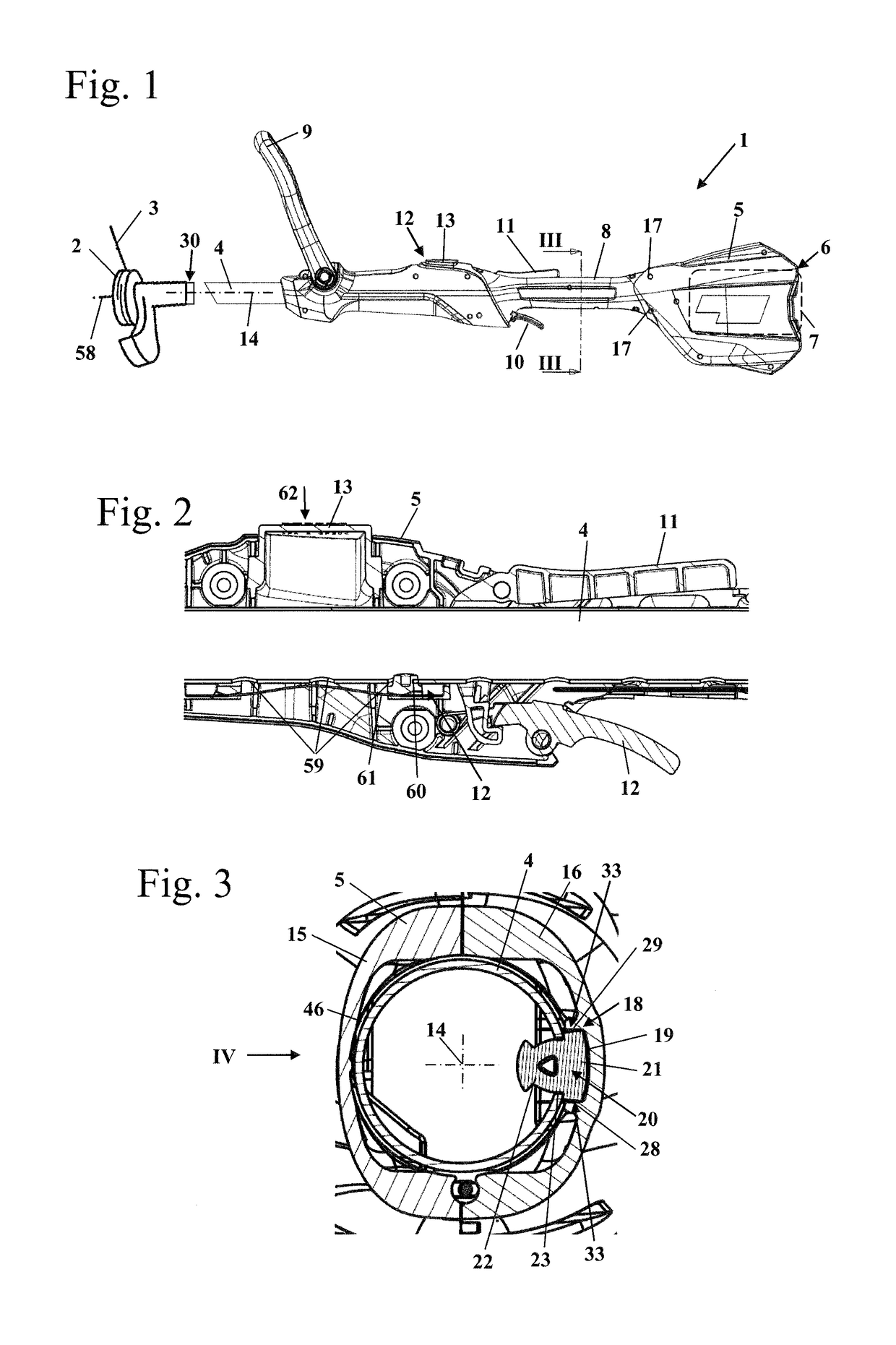
[0041]FIG. 1 shows a lawn trimmer 1 as an embodiment of a handheld work apparatus. The lawn trimmer 1 has a tool head 2 on which a cutting filament 3 is held. The tool head 2 is arranged at a first end 30 of a guide tube 4. During operation, the tool head 2 rotates about a rotational axis 58. A second end 31 (not shown in FIG. 1) of the guide tube 4 (FIG. 4) protrudes into a housing 5 of the lawn trimmer 1. A receptacle 6 for a battery 7 is formed on the housing 5. The receptacle 6 and the battery 7 are illustrated schematically in FIG. 1. If the lawn trimmer 1 is not battery-operated, but rather connected by a cord, a cord for connection to an energy supply can be secured on the housing 5. An internal combustion engine can also be provided for driving the lawn trimmer 1. A handle 8 is formed on the housing 5, the handle, in the embodiment, surrounding the guide tube 4, as FIG. 1 shows. In addition, a bale handle 9 is mounted pivotably on the housing 5. Operator-controlled levers 10...


PUM


Abstract

An arrangement of a housing and a guide tube is provided wherein one end of the guide tube is held in the housing. The position of the guide tube is adjustable relative to the housing in the direction of the longitudinal center axis of the guide tube. A rotation stop stops swiveling of the guide tube relative to the housing and includes a guide part. The guide part is mounted in one of the guide tube and housing. A longitudinal wall runs in the direction of the axis on the other one of the guide tube and housing. The longitudinal wall interacts with the guide part during swiveling of the guide tube about its axis. The guide part is tiltable relative to the guide tube about a tilt axis. The tilt axis runs along the guide tube and at a distance (a, b) from the axis of the guide tube.

Description

CROSS REFERENCE TO RELATED APPLICATION[0001]This application claims priority of European patent application no. 16400032.5, filed Jul. 25, 2016, the entire content of which is incorporated herein by reference.FIELD OF THE INVENTION[0002]The invention relates to an arrangement of housing and guide tube and to a handheld work apparatus with an arrangement of a housing and a guide tube.BACKGROUND OF THE INVENTION[0003]U.S. Pat. No. 5,933,966 discloses a handheld brushcutter which has a telescopic guide tube. For this purpose, the guide tube is held in the handle housing in a length-adjustable manner. In order to secure the rotational position during the adjustment, a bolt is provided which is held on the guide tube and projects into a longitudinal groove of the housing.[0004]The housing of work apparatuses of this type is customarily constructed from two housing shells which are connected to each other, for example are screwed to each other, at a plurality of connecting interfaces. The...

Claims


Application Information

Patent Timeline
IPC IPC(8): B25F5/02B25G1/04A01D34/90B65B51/30
CPCB25F5/028B65B51/306A01D2034/907A01D34/90B25G1/04A01D34/68A01D34/81A01D34/82B25F5/026
Inventor FOERSTNER, DIRKFAILENSCHMID, MARTINFRENCEL, KONRAD
Owner ANDREAS STIHL AG & CO KG
Why Eureka
Try Eureka