
Combined backup camera and driver alertness system for a vehicle

Inactive Publication Date: 2013-06-13
FORD GLOBAL TECH LLC
View PDF3 Cites 10 Cited by
  • Summary
  • Abstract
  • Description
  • Claims
  • Application Information

AI Technical Summary

Benefits of technology

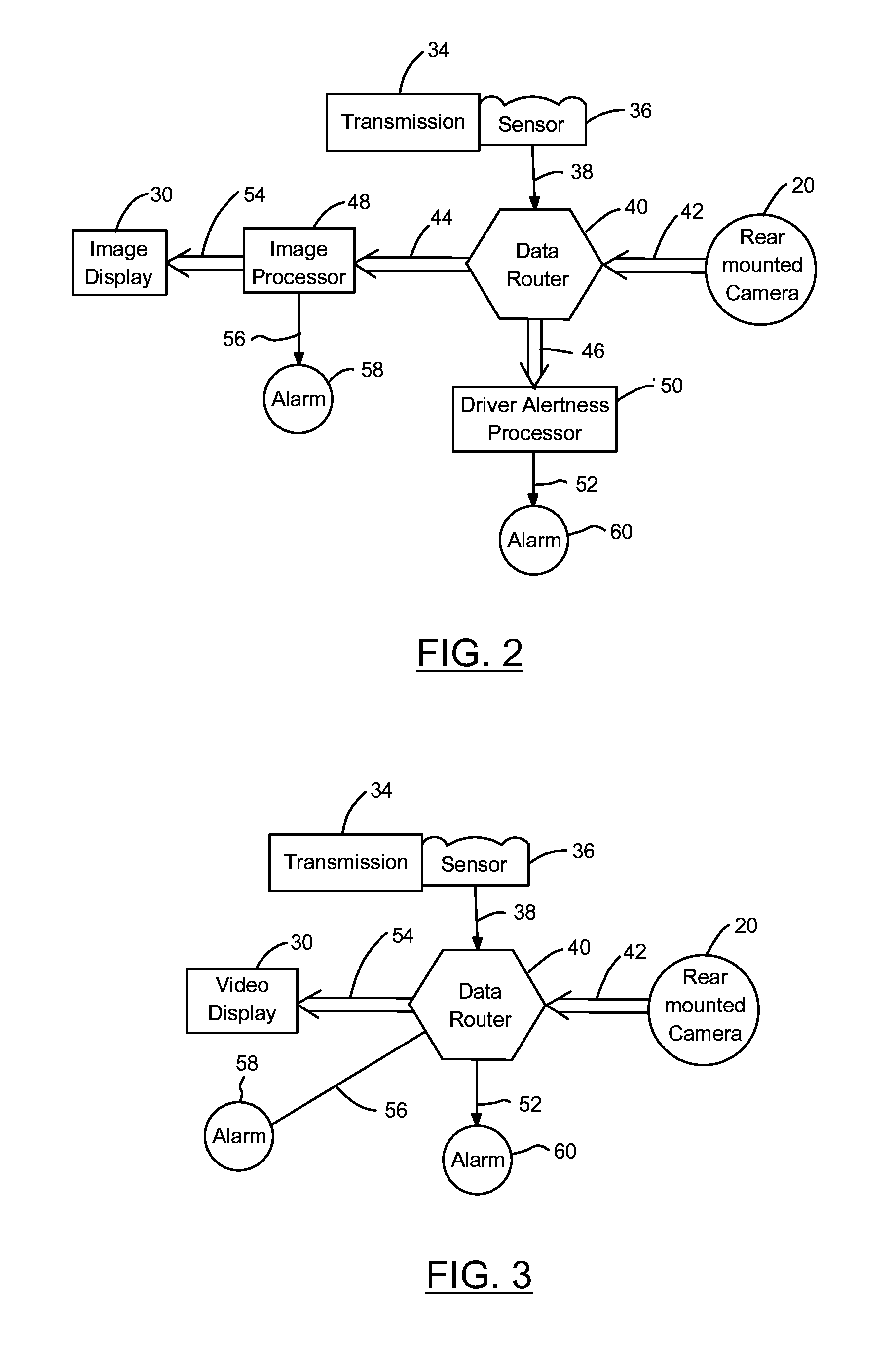
This patent is about a new system that combines a backup camera and a driver alertness system for a vehicle. It includes an imaging device that captures images of the rear of the vehicle, a sensor that detects if the vehicle is moving in reverse, and a driver alertness processor that displays the images on a screen. The system also has a data router that sends the images to the processor when the sensor detects movement or to the display when the sensor detects the vehicle is moving in reverse. The technical effect of this patent is to provide a more advanced and efficient system for improving driver safety and alertness by providing a combination of a backup camera and a driver alertness system.

Problems solved by technology

When a vehicle is traveling in a reverse direction, the potential exists for collisions with both stationary and moving objects such as fire hydrants, guardrails, other vehicles, pedestrians, bicycle riders, children, animals, etc.
Driver fatigue is also a known causes of accidents, particularly when the vehicle is traveling in a forward direction.
Externally mounted camera and other road monitoring devices can be affected by weather conditions, such as wet roads, rain, snow, etc. that can partially obstruct the view of the lane markers on the road.
Additionally, road hazards (such as stones and other debris) also can damage external monitoring devices.
However, in this location, the camera is located relatively far from the surface of the road and, consequently, must “look” at the road from over the vehicle hood.
In addition, when the camera is located within the passenger compartment of the vehicle, the front windshield may distort the images that are captured thereby.

Method used


Image

  • Combined backup camera and driver alertness system for a vehicle
  • Combined backup camera and driver alertness system for a vehicle
  • Combined backup camera and driver alertness system for a vehicle

Examples


Embodiment Construction

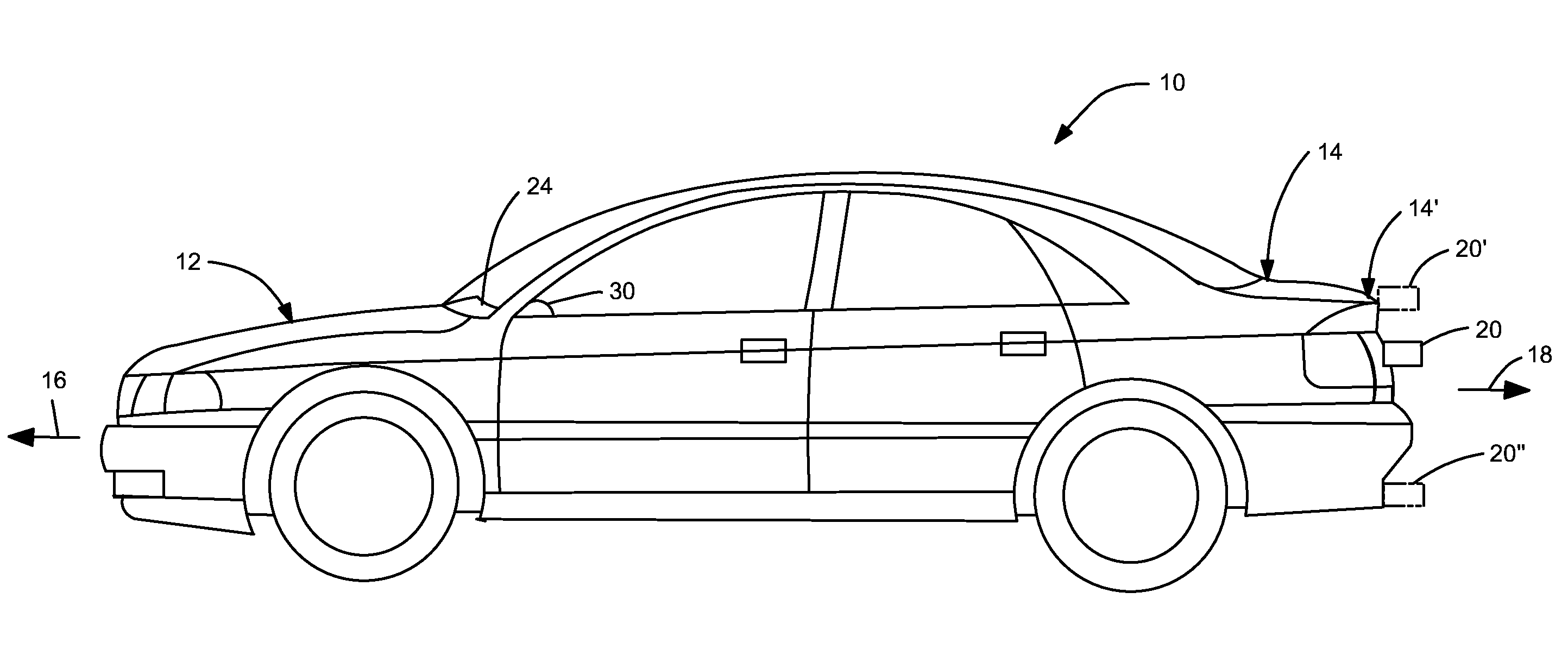
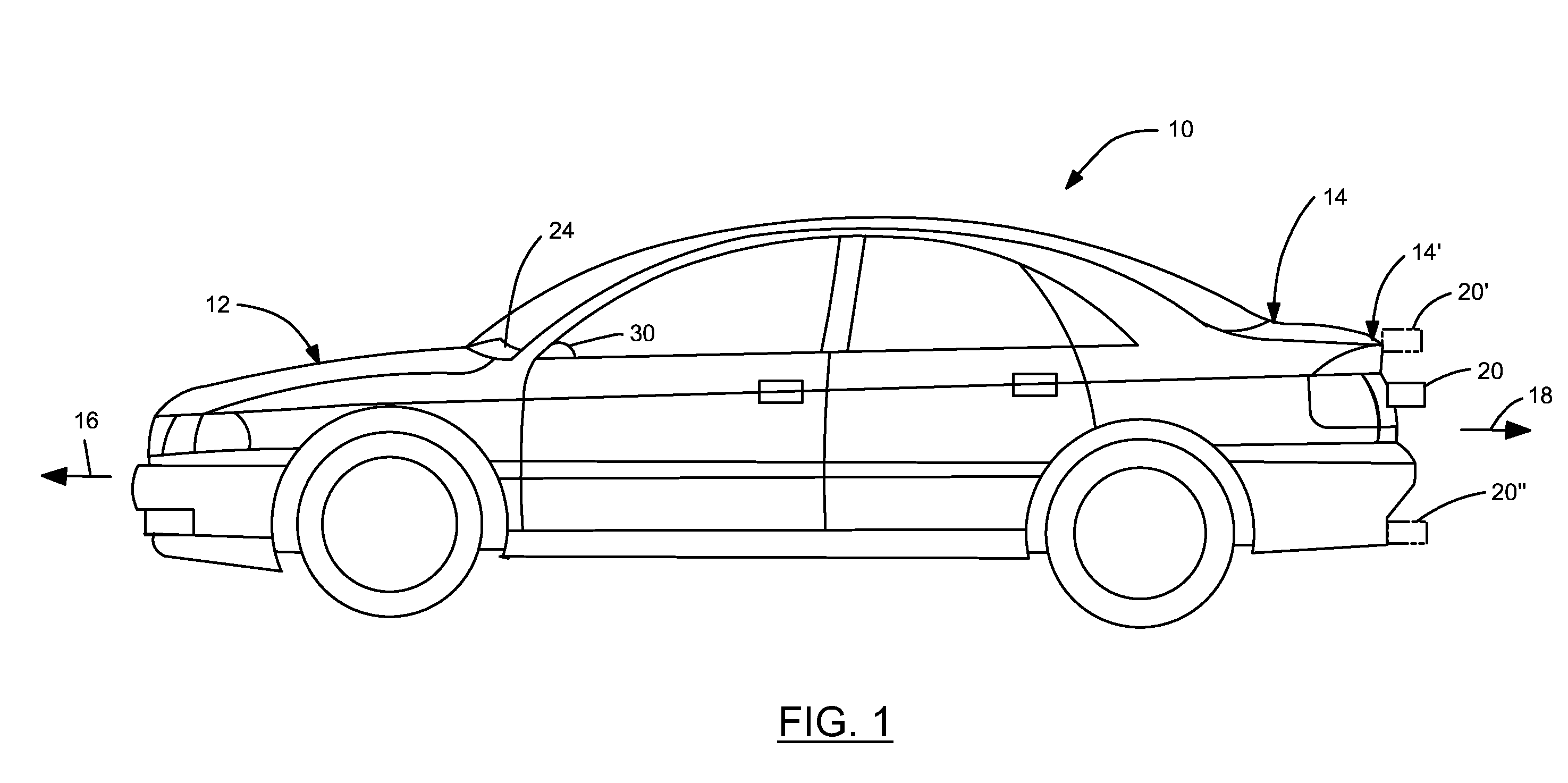
[0010]Referring now to the drawings, there is illustrated in FIG. 1 a vehicle 10 that includes a front portion 12 and a rear portion 14. As is well known in the art, the vehicle 10 is designed to operate in either a forward direction 16 or a rearward direction 18. An imaging device, such as a camera 20, is supported on the rear portion 14 of the vehicle 10, just above the license plate in the illustrated embodiment. Alternatively, as shown in phantom in FIG. 1, the camera 20 may be supported near on a trunk lid 20′ or on a rear bumper 20″. Preferably, the camera 20 is located close to a rearward most portion of the vehicle 14′ so that the camera 20 does not have to be aimed over the trunk lid 20′. This positioning also allows the camera 20 to capture areas immediately behind the vehicle 10. The camera 20 is preferably provided with a wide angle or fish-eye lens that can cover a wide area over a short distance, which is suitable for use in both backup imaging and lane departure warni...


PUM


Abstract

A combined backup camera and driver alertness system for a vehicle includes an imaging device that is adapted to be supported on a vehicle for capturing images adjacent a rearward portion of the vehicle. A sensor is provided that generates a signal when either (1) a transmission contained in the vehicle is operated in the rearward operating mode or (2) the vehicle is actually moved in the rearward direction. The system also includes a driver alertness processor and an image display. A data router routes the images from the imaging device to the driver alertness processor when not the signal is generated by the sensor and to the image display when the signal is generated by the sensor.

Description

BACKGROUND OF THE INVENTION[0001]This invention generally relates to camera-based obstacle avoidance systems for vehicles. In particular, this invention relates to an improved structure for a combined backup camera and driver alertness system for a vehicle.[0002]When a vehicle is traveling in a reverse direction, the potential exists for collisions with both stationary and moving objects such as fire hydrants, guardrails, other vehicles, pedestrians, bicycle riders, children, animals, etc. To reduce the potential for collisions, some vehicles are provided with obstacle avoidance systems that use rearwardly viewing camera that provide the vehicle operator enhanced ability to view objects at the rear of the vehicle. These camera-based obstacle avoidance systems display images from the camera on a display, allowing a driver of the vehicle to more easily see objects that might otherwise be hidden from his or her view. These camera-based obstacle avoidance systems can also include an ima...

Claims


Application Information

Patent Timeline
IPC IPC(8): H04N7/18
CPCB60R1/00B60R2300/8093B60R2300/301B60R1/26
Inventor RAO, MANOHARPRASAD K.CUDDIHY, MARK A.
Owner FORD GLOBAL TECH LLC
Learn More