Method of reducing transmission power and terminal thereof

a technology of transmission power and terminal, which is applied in the direction of power management, sustainable buildings, wireless commuication services, etc., can solve the problems of limited bandwidth, path loss, shadowing, and fading of wireless channels, so as to reduce transmission power, reduce transmission power, and reduce transmission power

Active Publication Date: 2013-06-13
LG ELECTRONICS INC
View PDF3 Cites 24 Cited by
  • Summary
  • Abstract
  • Description
  • Claims
  • Application Information

AI Technical Summary

Benefits of technology

[0053]Another aspect of the detailed description is to provide a method of reducing transmission power and a terminal thereof, which can limit power for maximum transmit power in carrier aggregation.
[0054]Still another aspect of the detailed description is to provide a method of reducing transmission power and a terminal thereof, which can limit power for maximum transmit power in a clustered discrete Fourier transform-spread-orthogonal frequency division multiplexing (DFT-s-OFDM) scheme.
[0055]To achieve these and other advantages and in accordance with the purpose of this specification, as embodied and broadly described herein, there is provided a method of reducing tr

Problems solved by technology

However, wireless channels suffer from several problems such as path loss, shadowing, fading, noise, limited bandwidth, power limitation of terminals and inter-user interference.
Other challenges in the design of the radio communication system include resource allocation, mobility issues related to rapidly changing physical channels, portability and design for providing security and privacy.
When a transmission channel suffers from deep fading, if another version

Method used


Image

  • Method of reducing transmission power and terminal thereof
  • Method of reducing transmission power and terminal thereof
  • Method of reducing transmission power and terminal thereof

Examples


Embodiment Construction

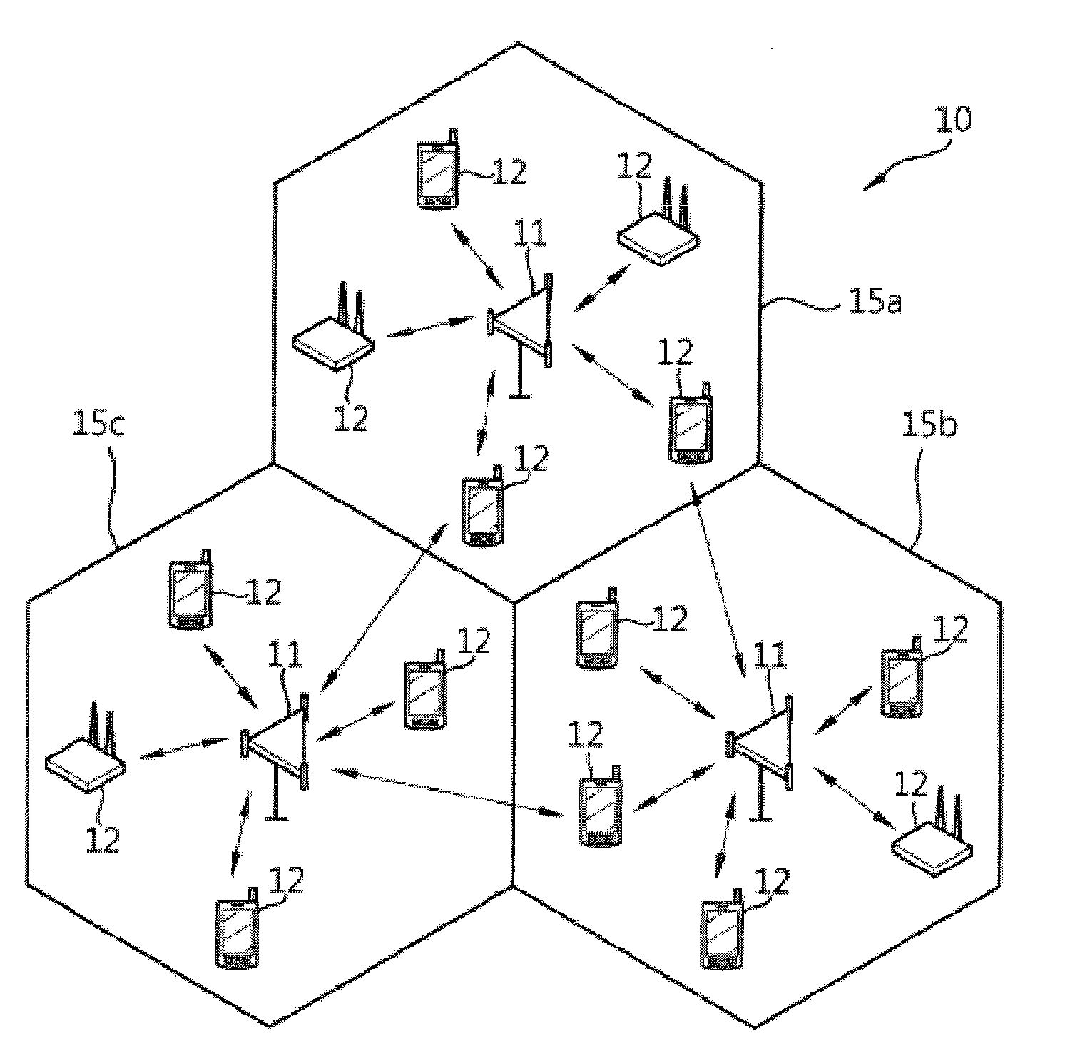
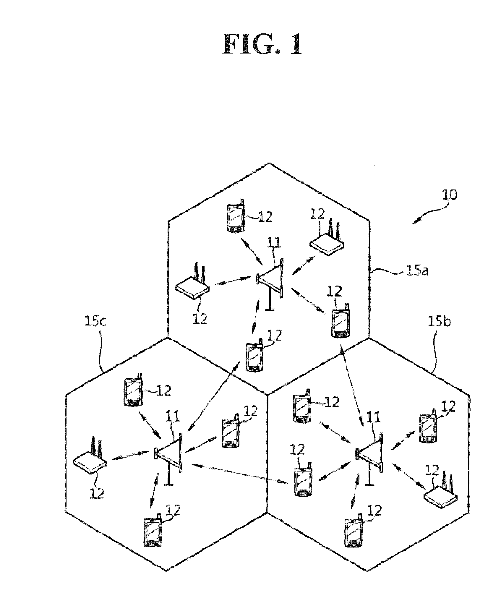
[0087]The following technology may be used in various multiple access schemes such as code division multiple access (CDMA), frequency division multiple access (FDMA), time division multiple access (TDMA), orthogonal frequency division multiple access (OFDMA) and single carrier-frequency division multiple access (SC-FDMA). The CDMA may be implemented by a radio technology such as universal terrestrial radio access (UTRA) or CDMA2000. The TDMA may be implemented by a radio technology such as a global system for mobile communications (GSM) / general packet radio service (GPRS) / enhanced data rates for GSM evolution (EDGE). The OFDMA may be implemented by a radio technology such as institute of electrical and electronics engineers (IEEE) 802.11 (Wi-Fi), IEEE 802.16 (WiMAX), IEEE 802.20 or evolved UTRA (E-UTRA). The UTRA is a portion of a universal mobile telecommunications system (UMTS). 3rd generation partnership project (3GPP) long term evolution (LTE) is a portion of an evolved UMTS (E-...


PUM


Abstract

A method of reducing transmission power is provided. In the method, a signal is transmitted by performing maximum power reduction (MPR) on maximum output power for the signal to be transmitted, when multi-cluster transmission is performed in a single component carrier. Here, the MPR is performed differently depending on a resource allocation ratio A. The resource allocation ratio A is defined as a ratio between NRB<sub2>—</sub2>agg and NRB<sub2>—</sub2>alloc. The NRB<sub2>—</sub2>agg represents the number of resource blocks (RBs) in a channel band, and the NRB<sub2>—</sub2>alloc represents the total number of RBs transmitted at the same time.

Description

CROSS-REFERENCE TO RELATED APPLICATION[0001]Pursuant to 35 U.S.C. §119(a), this application claims the priority benefit to U.S. Provisional Applications No. 61 / 568,150 (filed Dec. 7, 2011), No. 61 / 579,639 (filed Dec. 22, 2011) and No. 61 / 591,277 (filed Jan. 27, 2012) and the benefit of earlier filing date and right of priority to Korean Application No. 10-2012-0018182, filed on Feb. 22, 2012, the contents of which is incorporated by reference herein in its entirety.BACKGROUND OF THE INVENTION[0002]1. Field of the Invention[0003]The present disclosure relates to a method of reducing transmission power and a terminal thereof.[0004]2. Background of the Invention[0005]Recently, studies on a next-generation multimedia radio communication system have been actively conducted. The radio communication system requires a system that can process various information including images, radio data, etc. in lieu of services mainly using voice and transmit the information. The object of the radio com...

Claims


Application Information

Patent Timeline
IPC IPC(8): H04W52/02H04W72/04
CPCH04W72/0453H04L7/007H04L27/2614H04W72/0413H04W52/367H04W52/34Y02B60/50H04W52/365H04W52/06H04W52/243H04W72/0473H04W72/21
Inventor LIM, SUHWANJUNG, MANYOUNGYANG, YOONOHLEE, SANGWOOK
Owner LG ELECTRONICS INC
Why Eureka
Try Eureka