Artificial teethridge and fang

a technology of artificial teeth and fangs, applied in the field of dental fixtures, can solve the problems of reducing the capacity of force conduction and discontinuous transmission of force, and achieve the effect of reducing the capacity of force conduction and loading force stably and uniformly

Inactive Publication Date: 2013-06-13
CHEN LIEH TANG +1
View PDF15 Cites 9 Cited by
  • Summary
  • Abstract
  • Description
  • Claims
  • Application Information

AI Technical Summary

Benefits of technology

[0014]Moreover, the bottom surface of the artificial teethridge designs a complementary structure which can be tightly matched and fixed on the top surface of the alveolar bone without any gap (i.e. designs the bottom of the artificial teethridge having the concave surfaces to match the convex surfaces of the alveolar bone, or having the convex surfaces to match the concave surfaces of the alveolar bone, the concave and convex are complementary to each other. That is to say, the bottom surface of the artificial teethridge having a complementary structure tightly matched the top surface of the alveolar bone). Through this complementary arrangement, the loading force which transmits from the prosthesis can be spread and transmitted to each point of the top surface on the strong cortical bone of the alveolar bone completely and uniformly. This structure has mechanical support function like so-called “raft foundation” of architecture, which loads the chewing force transmitted from the prosthesis by each point of the top surface on the alveolar bone uniformly. The present invention uses the “raft foundation” in substitution for the traditional “pile foundation”, thus the structure of the present invention will load the force stably and uniformly. That is to say, this mechanical support structure can load the chewing force completely and uniformly.
[0015]Besides, to avoid the weak point exist at this dental structure, the present invention does not combine separated parts of the structure by screws. Thereby this structure has no connecting portion which may cause a discontinuous transmission of force and reduce the capacity of force conduction. The present invention designs an integral structure which comprises the main part of force conduction and force supporting, so that it forms a strong and stable structure with great force support, uniform force dispersion, firm fixation, and well force conduction.
[0019]3. The structure of the artificial teethridge, the fang and the prosthesis are specifically an integral structure without any part may be disassembled, which will not cause a fragile structure and a poor force conduction.

Problems solved by technology

Thereby this structure has no connecting portion which may cause a discontinuous transmission of force and reduce the capacity of force conduction.

Method used


Image

  • Artificial teethridge and fang
  • Artificial teethridge and fang
  • Artificial teethridge and fang

Examples


Embodiment Construction

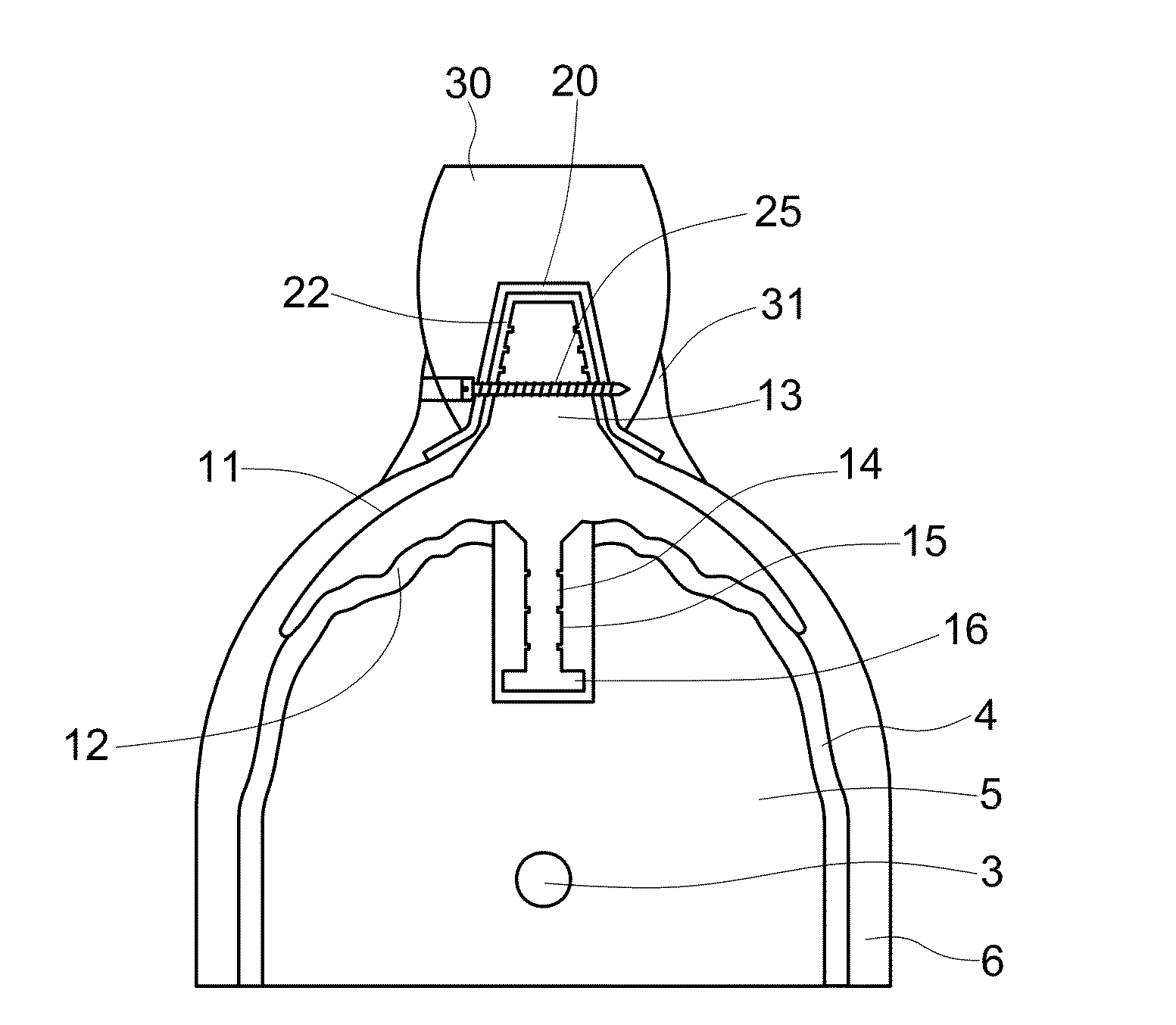
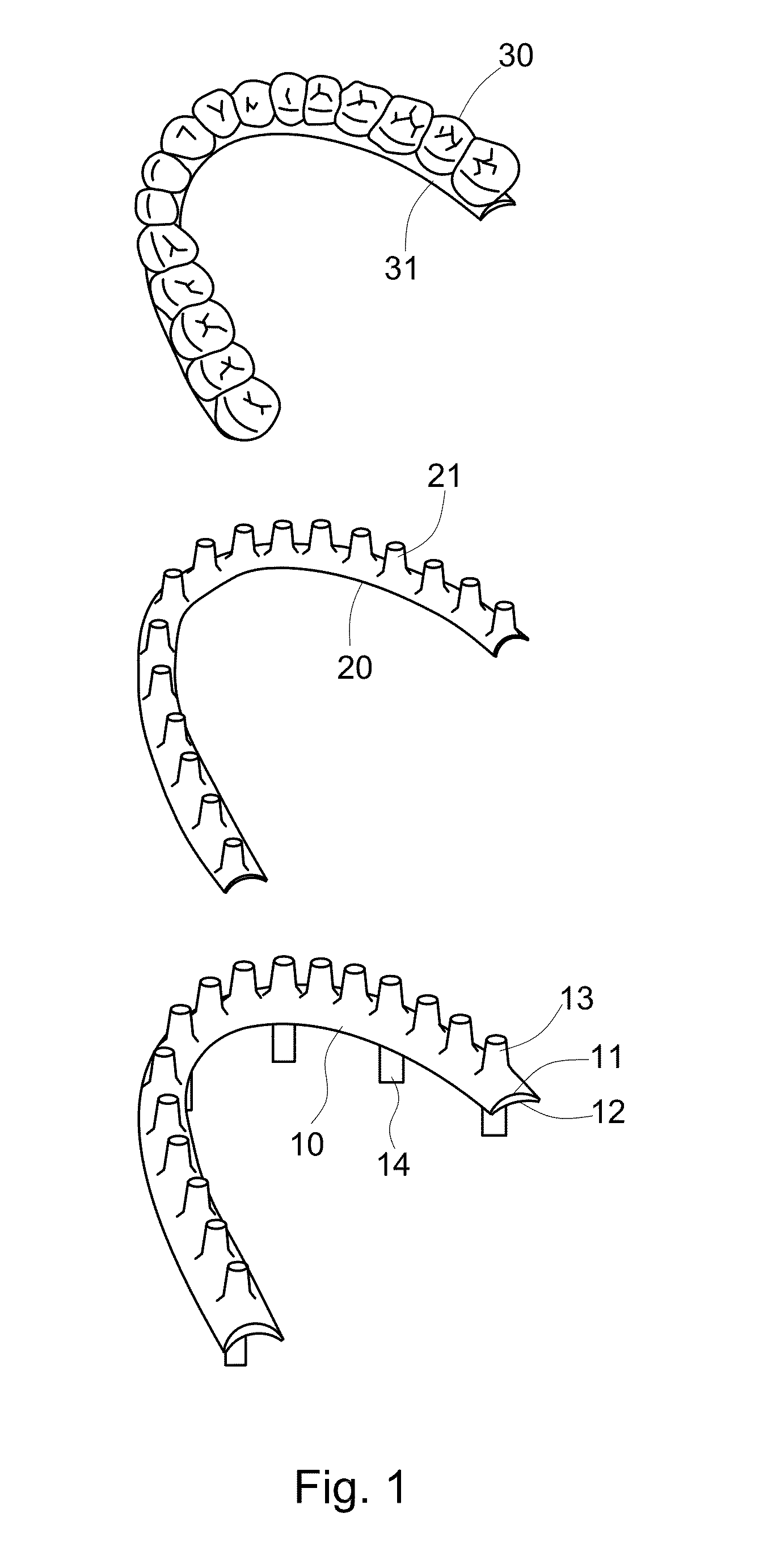
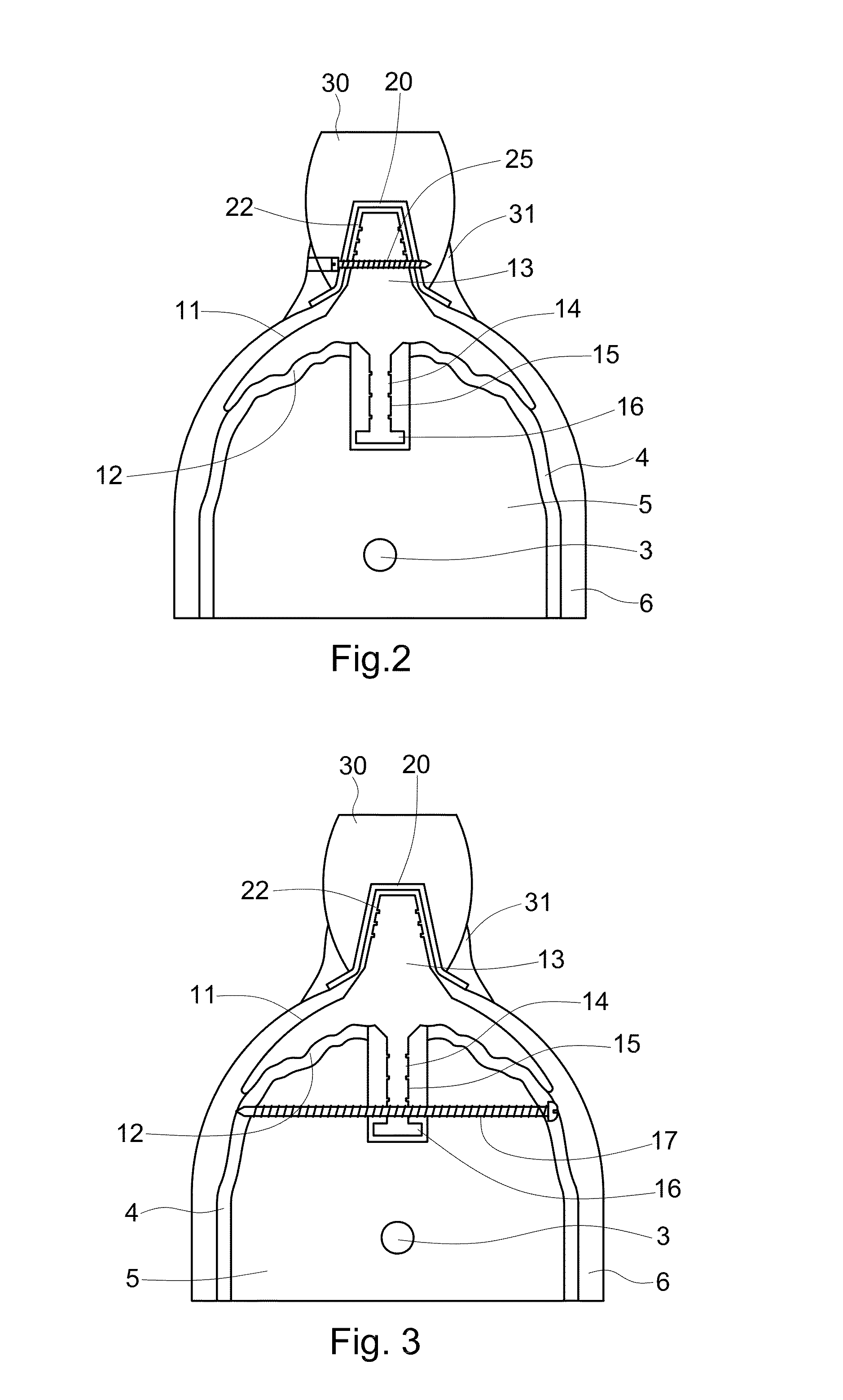
[0035]As shown in FIG. 1 and FIG. 2, the first preferred embodiment of the present invention includes an artificial teethridge 10, a prosthesis base 20 and a prosthesis 30.

[0036]The artificial teethridge 10 has a crescent cross-section, which has a shape corresponding to the maxillary or the mandible of human, and the thickness of the artificial teethridge is relatively thicker at central part and gradually becomes thinner toward two lateral sides. The artificial teethridge 10 has an arched top 11 and an arched bottom 12. On the top 11 of the artificial teethridge 10 form integral with the fang 13, and the fang 13 has a narrower fang top and a wider fang bottom. The bottom surface 12 of the artificial teethridge 10 designs a complementary structure which can be tightly matched and fixed on the top of the alveolar bone 5 without any gap, whereby the bottom 12 of the artificial teethridge 10 forms a mechanical support structure. The loading force, which is transmitted from the prosthe...


PUM


Abstract

A structure of the artificial teethridge, the fang and the prosthesis includes an artificial teethridge which has an arched top and an arched bottom, wherein the top and the bottom of the artificial teethridge are curved toward the same direction. The thickness of the artificial teethridge is relatively thicker at central part and gradually becomes thinner toward two lateral sides. A fang form integral on the top of the artificial teethridge. The artificial teethridge, the fang and prosthesis are an integral structure, whereby the artificial teethridge, the fang and the prosthesis form a mechanical conduction structure. The bottom surface of the artificial teethridge has a complementary structure which can be tightly matched and fixed on each point of the top surface of the alveolar bone without any gap, whereby the bottom of the artificial teethridge further includes a fastening fixture. A dental neck form integral between the artificial teethridge and prosthesis, the dental neck being formed in a waisted shape that is narrower at middle section and gradually becomes wider toward to two terminal sections.

Description

CROSS-REFERENCE[0001]This application is a continuation-in-part (CIP) application of U.S. patent application Ser. No. 12 / 524,361, filed on Jul. 23, 2009.FIELD OF THE INVENTION[0002]The present invention relates to a structure of dental fixture, particularly relates to an integral structure of the artificial teethridge, the fang and the prosthesis which are fixed on the cortical bone of the alveolar bone. The artificial teethridge and fang can well spread and transmit the chewing force to the alveolar bone uniformly, and load the chewing force by entire top surface of the alveolar bone.DESCRIPTION OF THE RELATED ART[0003]In present days, there are many different methods to mount the denture. The earliest method is to directly mount the denture on the gingival. This method is quite simple, however, the patient usually have an uncomfortable feeling of having foreign body in the mouth, and can not chew the hard food. Other disadvantages include difficult to fix the denture on the jaw, a...

Claims


Application Information

Patent Timeline
Patent Type & Authority Applications(United States)
IPC IPC(8): A61C13/01A61C13/097A61C8/00
CPCA61C13/01A61C8/0022A61C8/0075A61C8/0068A61C8/0031A61C13/097
Inventor CHEN, LIEH-TANGCHEN, CHEN-CHU
Owner CHEN LIEH TANG
Why Eureka
Try Eureka