Locking support mechanism and exposure device of material exposure test box

A technology of exposure test and support mechanism, which is applied in the field of external exposure of space station materials, to achieve the effect of compact overall structure, stable and firm structure, and high space utilization rate

Active Publication Date: 2020-05-05
TECH & ENG CENT FOR SPACE UTILIZATION CHINESE ACAD OF SCI
View PDF8 Cites 4 Cited by
  • Summary
  • Abstract
  • Description
  • Claims
  • Application Information

AI Technical Summary

Problems solved by technology

[0024] The technical problem to be solved by the present invention is that there is no detachable inst...

Method used


Image

  • Locking support mechanism and exposure device of material exposure test box
  • Locking support mechanism and exposure device of material exposure test box
  • Locking support mechanism and exposure device of material exposure test box

Examples


Embodiment 1

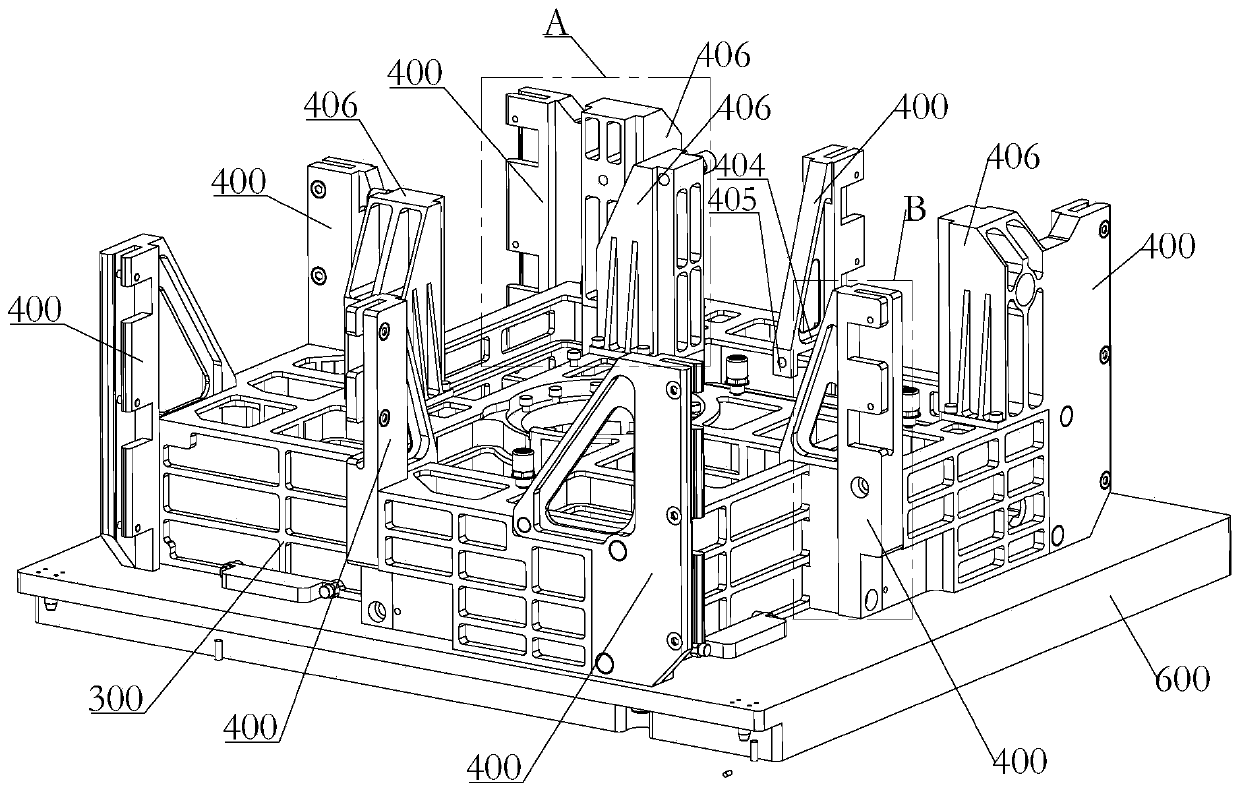
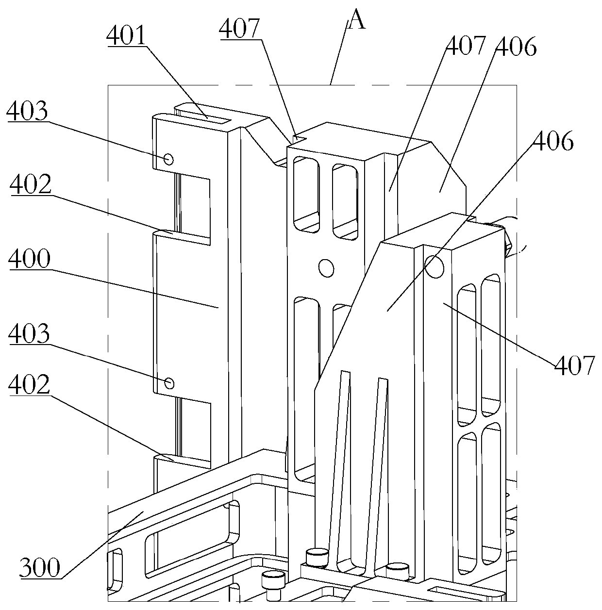
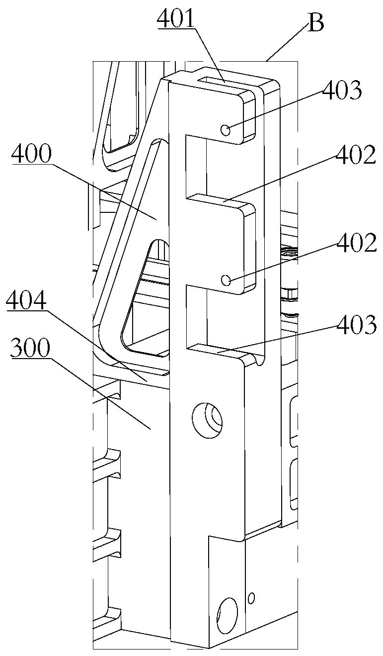
[0063] Such as Figure 1-Figure 7 As shown, the locking support mechanism of a material exposure test chamber in this embodiment includes a locking bracket 400 and a load-bearing mechanism 300. There are a plurality of locking brackets 400 and they are respectively vertically fixed on the load-bearing mechanism 300. On the outer peripheral side; one side of the locking bracket 400 is provided with a chute 401, a limit gap 402 is formed on the groove wall of the chute 401, and a guide locking member 403 is provided on the locking bracket 400, so that The guide locking member 403 is set through the two groove walls of the chute 401; the side walls of the test box 200 are respectively provided with baffle plates 201 arranged at intervals, and one end of the baffle plate 201 is connected to the test box An installation opening 208 is formed between the side walls of 200, and a partition rib 202 is provided between the baffle plate 201 and the side wall of the test box 200, and the...

Embodiment 2

[0084] Such as Figure 1-Figure 7 As shown, a material exposure test chamber exposure device in this embodiment includes the locking support mechanism and the base 600, the load-bearing mechanism 300 is installed on the base 600, and the locking bracket 400 is connected to the base 600. The base 600 is vertically arranged, the load-bearing mechanism 300 and the base 600 are polygonal structures respectively, and the corresponding sides are arranged in parallel, and at least one test box 200 is installed on each side of the load-bearing mechanism 300 After the test box 200 is opened, its exposed surface is arranged perpendicular to the base 600 and extends to both ends of the corresponding sides of the bearing mechanism 300 .

[0085] Specifically, such as Figure 1-Figure 7 As shown, the load-bearing mechanism 300 is an integrally formed structure. The load-bearing mechanism 300 is a quadrilateral structure, and one of the test boxes 200 is fixed on each of its four sides by ...


PUM


Abstract

The invention relates to a locking support mechanism and an exposure device of a material exposure test box. The locking support mechanism comprises locking brackets and a bearing mechanism, and a plurality of locking brackets are correspondingly and vertically fixed to the peripheral side of the beating mechanism; sliding grooves are formed in one side edges of the locking brackets, limiting notches are formed in the groove walls of the sliding grooves, guide locking parts are arranged on the locking brackets, and penetrate through two groove walls of the sliding grooves; baffles which are arranged at intervals with the side walls of a test box are correspondingly arranged on the side walls of the test box, mounting ports are formed among one ends of the baffles and the side walls of thetest box, separating bars are arranged among the baffles and the side walls of the test box, the baffles and the side walls of the test box are separated by the separating bars to form a plurality ofmounting grooves which are formed up and down, and guiding ports are formed in the baffles; and wherein the groove walls formed with the limiting notches of the sliding grooves are inserted into the mounting grooves, the separating bars are inserted into the limiting notches, the guide locking parts are inserted into the guiding ports, and lock the baffles in the sliding grooves. According to thelocking support mechanism and the exposure device of the material exposure test box, the structure is stable and firm, and the environmental requirements of a space station can be met.

Description

technical field [0001] The invention relates to the field related to the external exposure of space station materials, in particular to a locking support mechanism and an exposure device for a material exposure test chamber. Background technique [0002] The material exposure test chamber provides an installation space and a closed environment for exposed materials. When performing space exposure tests on materials, due to the space station running along the orbit, the exposure device being transported on the ground, going up with the rocket, on-orbit transfer, and space cabin docking, etc. Both require a stable installation of the material exposure test chamber. In addition, in the process of going up with the rocket, the mechanical environment is relatively harsh, so the installation structure needs to bear a large vibration and impact environment. At present, there is no stable and detachable installation structure for the test box. [0003] Moreover, the movement mecha...

Claims


Application Information

Patent Timeline
IPC IPC(8): F16M13/02B64G4/00B64G1/66
CPCB64G1/66B64G4/00F16M13/022
Inventor 张聚乐张伟贵王乐天王珂唐善平王辅辅冯振华
Owner TECH & ENG CENT FOR SPACE UTILIZATION CHINESE ACAD OF SCI
Why Eureka
Try Eureka