Automatic chest compression device

a chest compression and automatic technology, applied in the field of chest compression devices, can solve the problems of not applying sufficient compression and placing a heavy physical burden on the rescuer, and achieve the effect of reliably giving chest compression without involving any complicated operation

Inactive Publication Date: 2013-06-13
NITTA KAZUFUKU
View PDF11 Cites 4 Cited by
  • Summary
  • Abstract
  • Description
  • Claims
  • Application Information

AI Technical Summary

Benefits of technology

[0027]The present invention can achieve excellent effect of giving chest compression reliably without involving any complicate operation.

Problems solved by technology

Meanwhile, the aforementioned chest compression necessitates a great deal of power of a rescuer, thereby placing a heavy physical burden on the rescuer.
In particular, if the rescuer is a woman or an elderly person, for example, sufficient compression may not be applied.

Method used


Image

  • Automatic chest compression device
  • Automatic chest compression device
  • Automatic chest compression device

Examples


Embodiment Construction

[0032]An example of an embodiment of the present invention will be described in detail below by referring to the drawings.

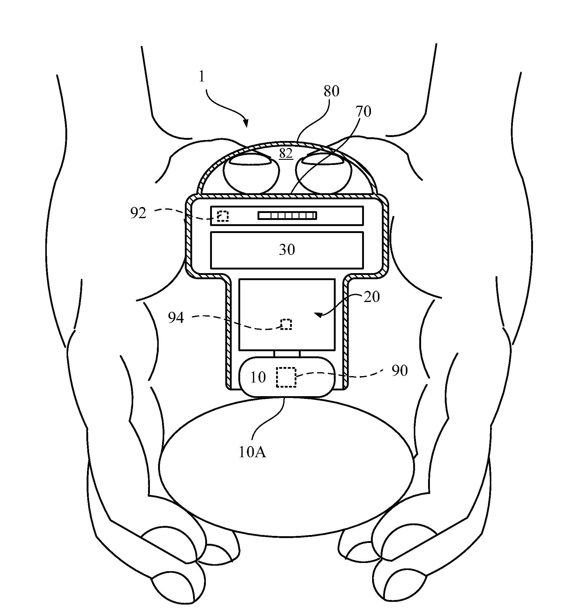
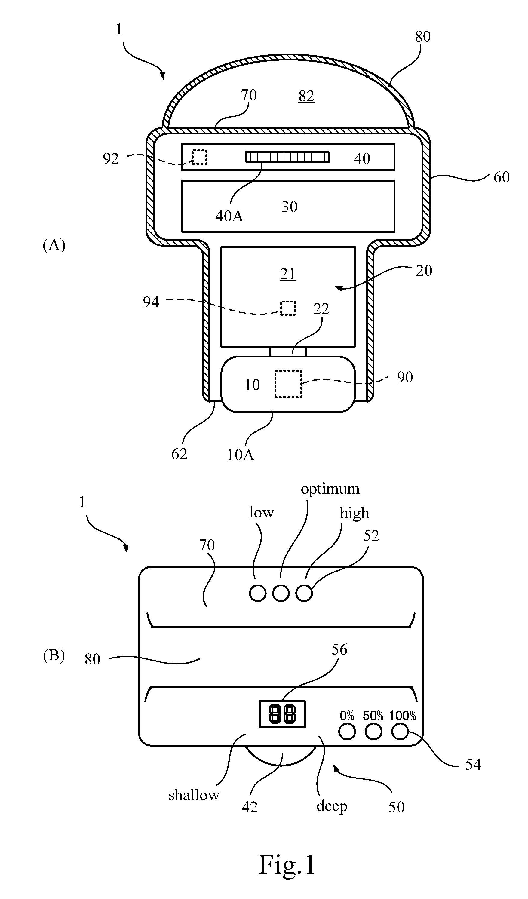
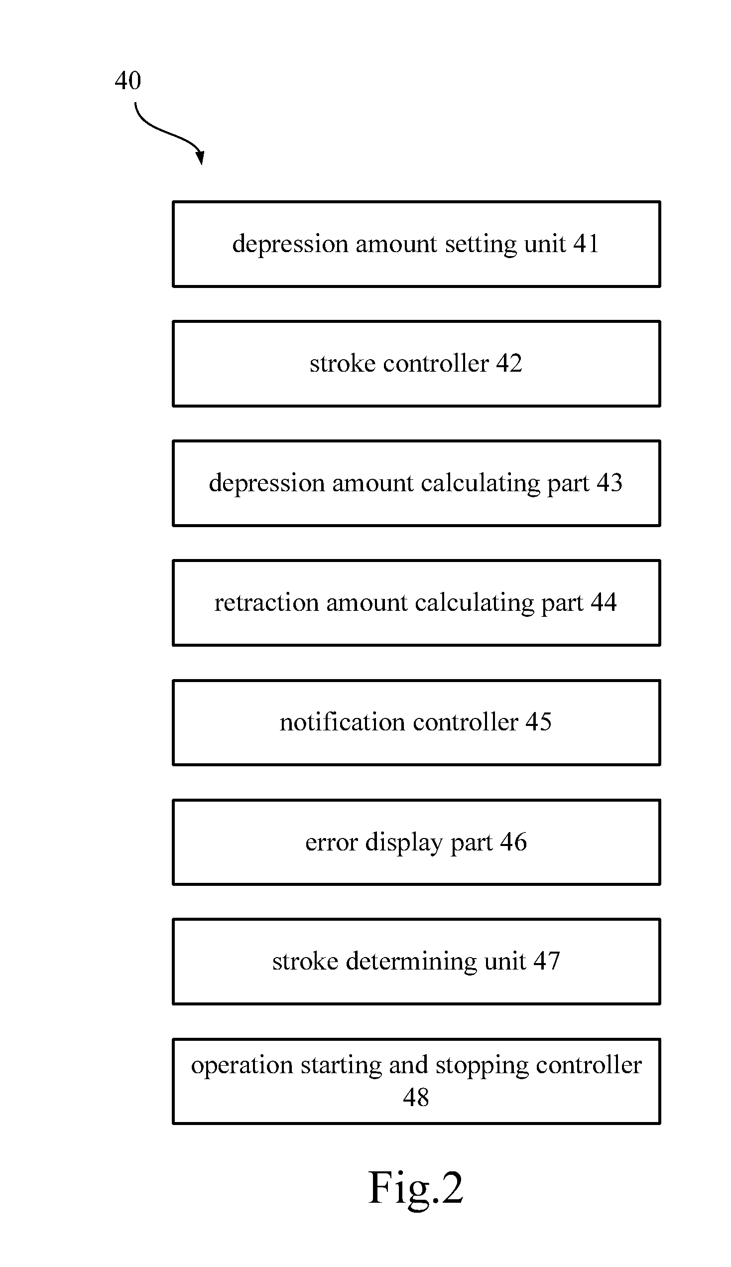
[0033]FIG. 1 shows the entire structure of an automatic chest compression device 1 according to the present embodiment. The automatic chest compression device 1 includes a pressure member 10 that makes abutting contact with the chest of a body, a driving unit 20 that makes the pressure member 10 move to and fro, a rechargeable battery 30 that supplies the driving unit 20 with electricity, a control unit 40 that controls the operation of the driving unit 20, a notifying unit 50 that transmits various information to a rescuer, a housing 60 that houses these components, and a pressure receiving unit 70 formed in the housing 60.

[0034]The pressure member 10 has a pressure surface 10A formed in a flat condition while directed downward. The pressure surface 10A is pressed against the chest of a body to depress the chest. At least the pressure surface 10A is covered with...


PUM


Abstract

An automatic chest compression device includes: a pressure member that makes abutting contact with the chest of a body; a driving unit that makes the pressure member move to and fro; a pressure receiving unit that allows rescuer's hands to receive a reaction force which is generated on the side of the driving unit when the chest of the body is compressed by the pressure member; and a control unit that calculates a substantial amount of depression of the chest by the pressure member, and controls a stroke of the pressure member given by the driving unit. As a result, chest compression can be applied reliably while any complicate operation is not required.

Description

TECHNICAL FIELD[0001]The present invention relates to an automatic chest compression device used for cardiac massage applied in response to arrest of respiration or pulsation, and relates to a device suitably applied for cardiopulmonary resuscitation of infants and children, for example.BACKGROUND ART[0002]In response to sudden arrest of a heart or respiration, sternum compression (cardiac massage) is applied to forcedly assist the respiration and the circulation of a body. Operation of this sternum compression is as follows. First, with both hands overlapping each other, a rescuer places the roots of the hands on a line connecting the nipples of a patient.[0003]Then, the rescuer applies a force to depress the sternum of the patient about 4 to 5 cm into the body. At this time, the rescuer straightens elbows to apply a force appropriately to the patient and to avoid physical exhaustion of the rescuer. This operation is repeated at a speed of about 100 times per minute. For example, t...

Claims


Application Information

Patent Timeline
Patent Type & Authority Applications(United States)
IPC IPC(8): A61H31/00
CPCA61H31/005A61H31/006A61H31/007A61H2201/123A61H31/00A61H2201/169A61H2201/5064A61H2201/5084A61H2201/1238
Inventor NITTA, KAZUFUKU
Owner NITTA KAZUFUKU
Why Eureka
Try Eureka