
Brace with elongated fenestrations

a brace and fenestration technology, applied in the field of braces, can solve the problems that the brace may lose the ability to properly support the limb, and achieve the effects of reducing weight, reducing profile, and simplifying the design and construction of the bra

Active Publication Date: 2013-06-13
3D SYST INC
View PDF4 Cites 18 Cited by
  • Summary
  • Abstract
  • Description
  • Claims
  • Application Information

AI Technical Summary

Benefits of technology

The present invention is a brace that has a unique structure that surrounds an injured limb to prevent movement. The brace has elongated spaces that are designed to fit snugly around the limb. These spaces are connected by beams and posts, which make the brace flexible and elastic. The brace also allows air to circulate around the limb, which can help to promote healing. The technical effect of this invention is to provide a comfortable and flexible brace that can help to protect and promote healing of an injured limb.

Problems solved by technology

Because the brace is a completely rigid structure a large gap between the limb and the brace can form and the brace may lose it ability to properly support the limb as it heals and is in a weakened state.

Method used


Image

  • Brace with elongated fenestrations
  • Brace with elongated fenestrations
  • Brace with elongated fenestrations

Examples


Embodiment Construction

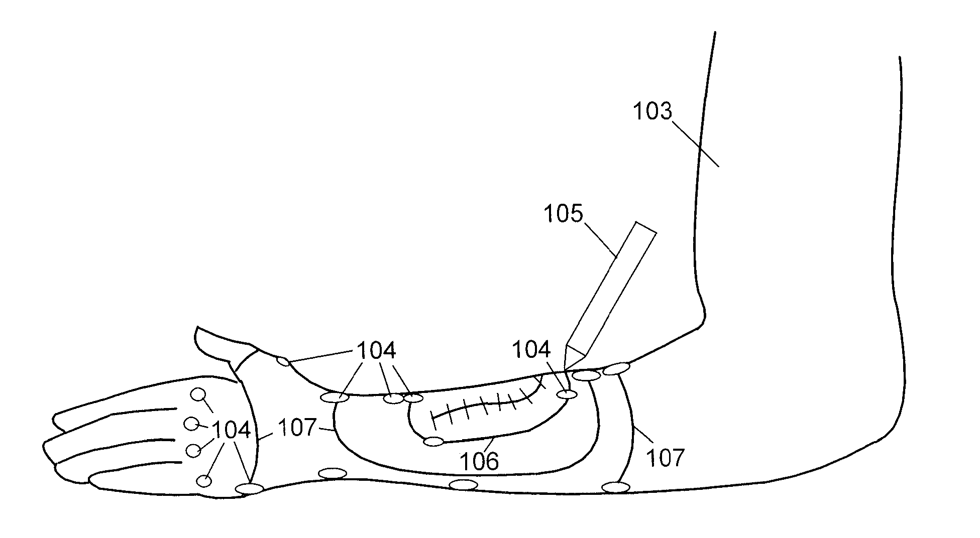
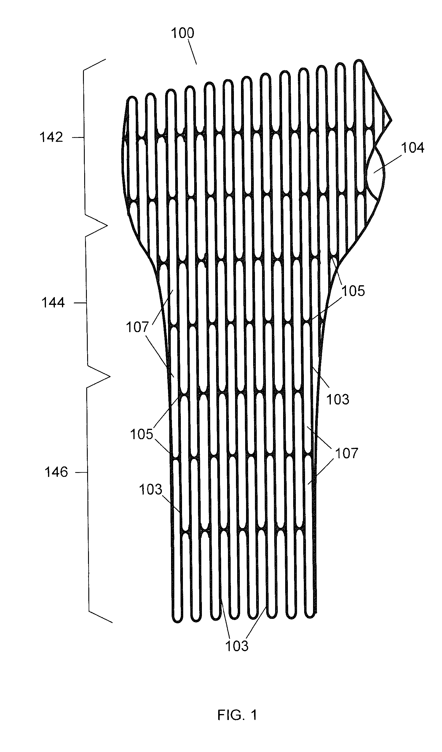
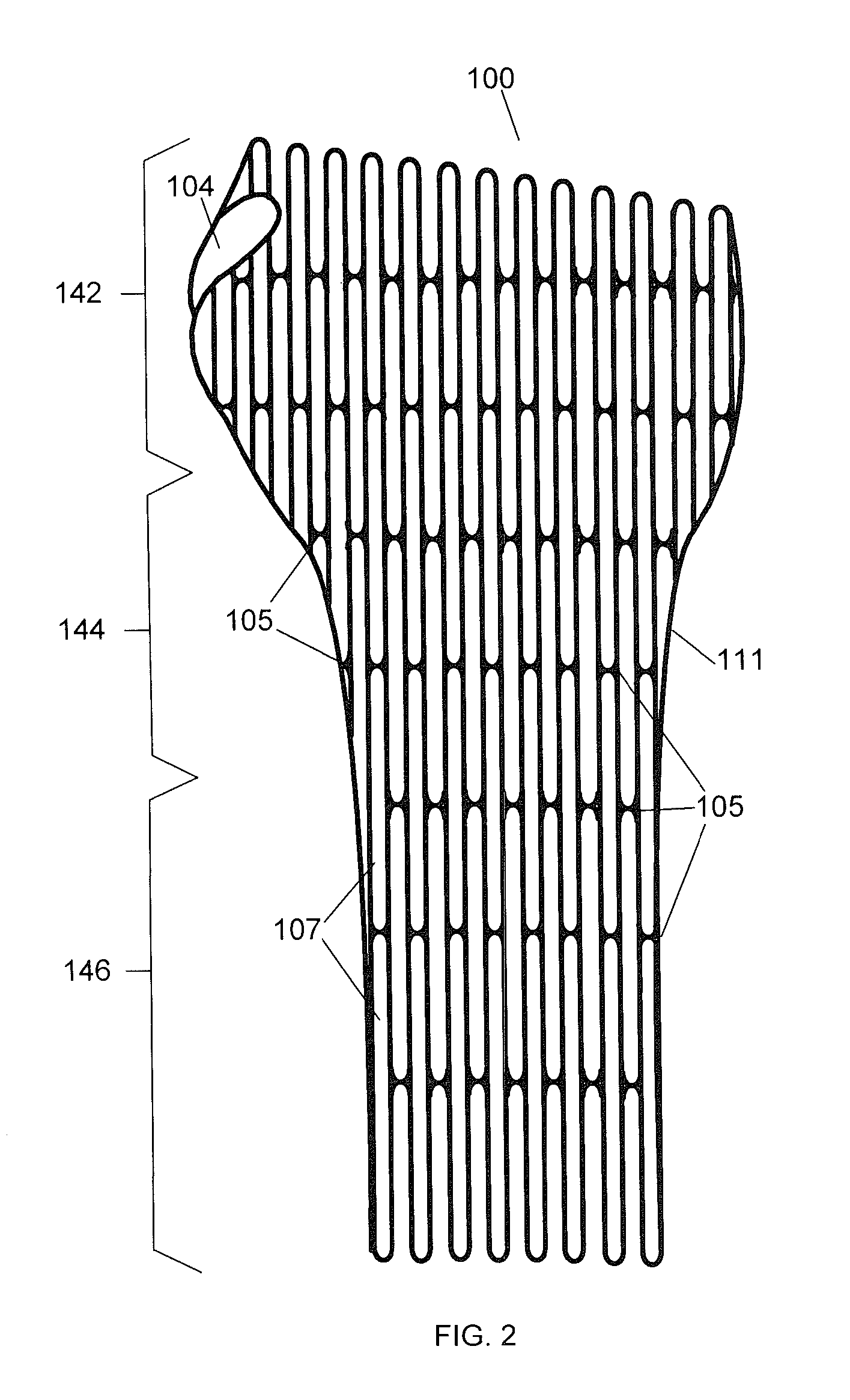
[0032]The present invention is directed towards a brace having a plurality of thin elongated beams that extend substantially in parallel along the length of the brace. The beams of the brace can be separated by a plurality of fenestrations that also extend substantially in parallel along the length of the brace. The adjacent beams are coupled together by posts that are substantially perpendicular to the beams. Each fenestration can be surrounded by two adjacent beams define the sides and two posts that define the ends of the fenestration. This configuration allows the brace to provide support for the limb and prevent bending but is also flexible and allows for radial expansion to provide a close fit with the limb.

[0033]FIG. 1 illustrates a top dorsal view, FIG. 2 illustrates a bottom palmar view and FIG. 3 illustrates a side unular view of an embodiment of a brace 100. In the illustrated embodiment, the brace 100 can be an arm brace 100 that at least partially surrounds the patient'...


PUM


Abstract

A brace has a plurality of elongated beams that extend in parallel along the length of the brace. The adjacent beams are coupled to posts that extend around the circumference of the brace in a staggered pattern and hold the beams in place around the brace. The beams and posts define a plurality of elongated fenestrations. The configuration of the beams and fenestrations allow the brace to be strong in compression and bending and also provide elastic radial expansion.

Description

CROSS REFERENCE TO RELATED APPLICATIONS[0001]This application claims priority to U.S. Provisional Application No. 61 / 720,878, “Bikini Brace” filed Oct. 31, 2012, U.S. Provisional Application No. 61 / 720,861, “Spiral Brace” filed Oct. 31, 2012 and U.S. Provisional Application No. 61 / 596,037, “Fracture Brace” filed Feb. 7, 2012 and is a continuation-in-part of PCT Patent Application. No. PCT / US2012 / 051612, “Adjustable Brace” filed Aug. 20, 2012 which claims priority to U.S. patent application Ser. No. 13 / 214,096, “Adjustable Brace” filed Aug. 19, 2011 which is a continuation-in-part of U.S. patent application Ser. No. 12 / 820,968, “Modular Custom Braces, Casts And Devices And Methods For Designing And Fabricating filed Jun. 22, 2010 which is a continuation-in-part of U.S. patent application Ser. No. 12 / 615,196, now U.S. Pat. No. 8,005,651, “Custom Braces, Casts and Devices And Methods For Designing And Fabricating” filed Nov. 9, 2009 which claims priority to U.S. Provisional Patent Appl...

Claims


Application Information

Patent Timeline
Patent Type & Authority Applications(United States)
IPC IPC(8): A61F5/01
CPCA61F5/013A61F5/01A61F5/05866A61F5/02A61F5/05841A61F5/0123B33Y80/00
Inventor SUMMIT, SCOTTTRAUNER, KENNETH B.
Owner 3D SYST INC
Learn More