
Bacteria Filter and Heating System

a technology of applied in the field of bacteria filter and heating system, can solve the problems of affecting the operation of ventilator system, etc., and can not overcome the ultimate buildup of condensed moisture on their own

Active Publication Date: 2013-06-20
12TH MAN TECH
View PDF9 Cites 7 Cited by
  • Summary
  • Abstract
  • Description
  • Claims
  • Application Information

AI Technical Summary

Benefits of technology

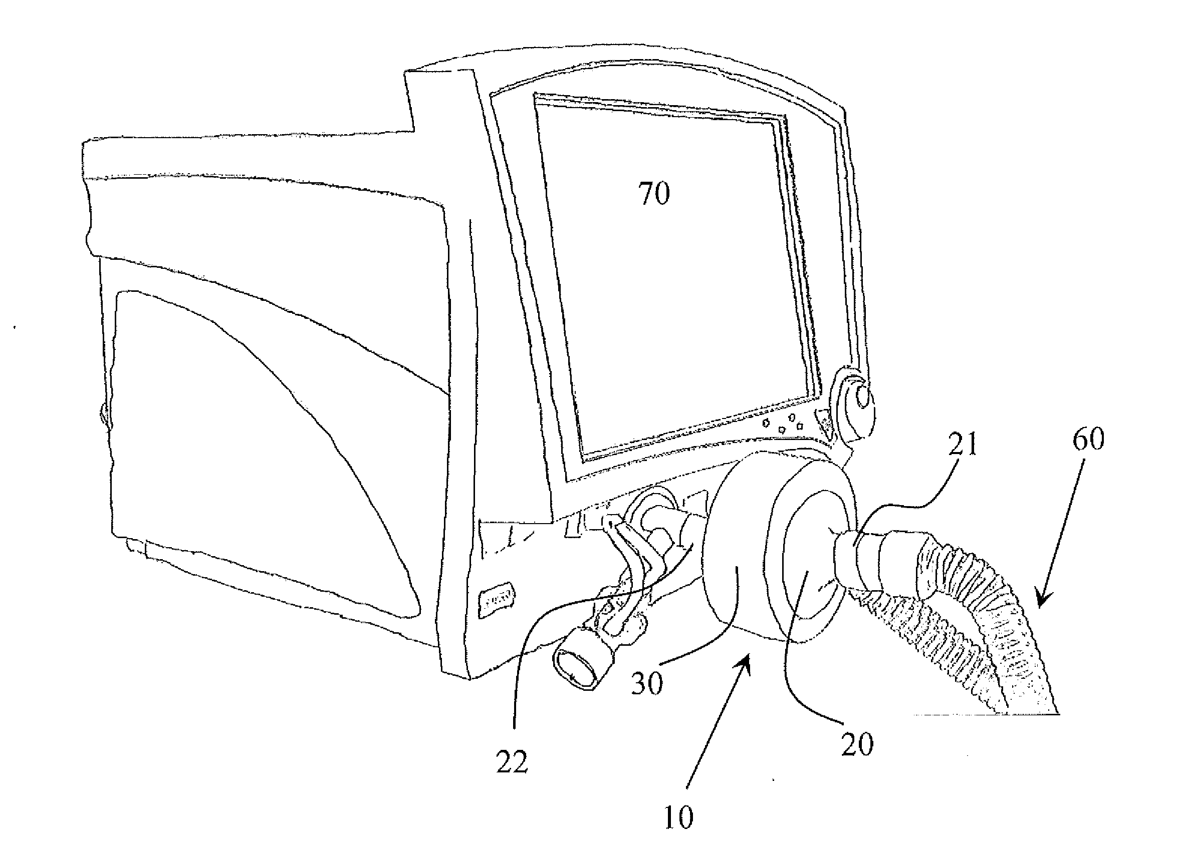
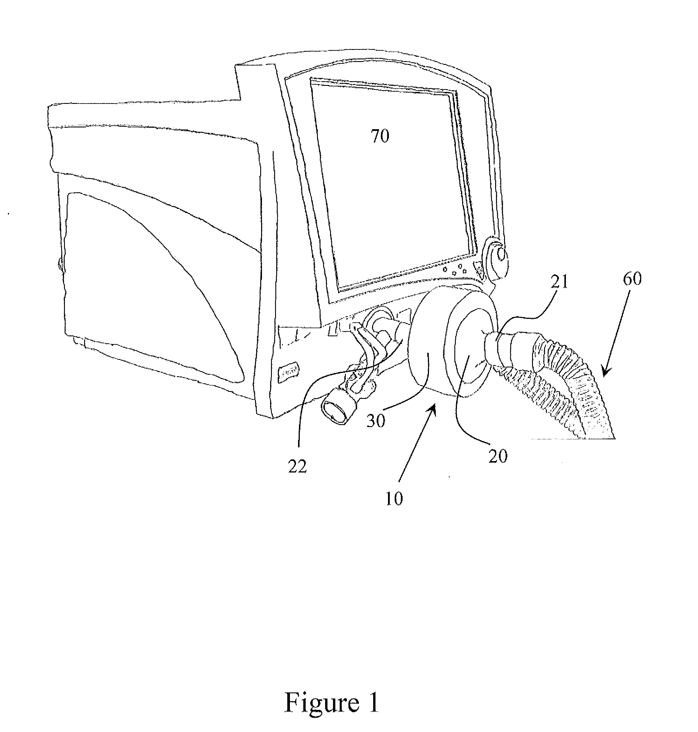
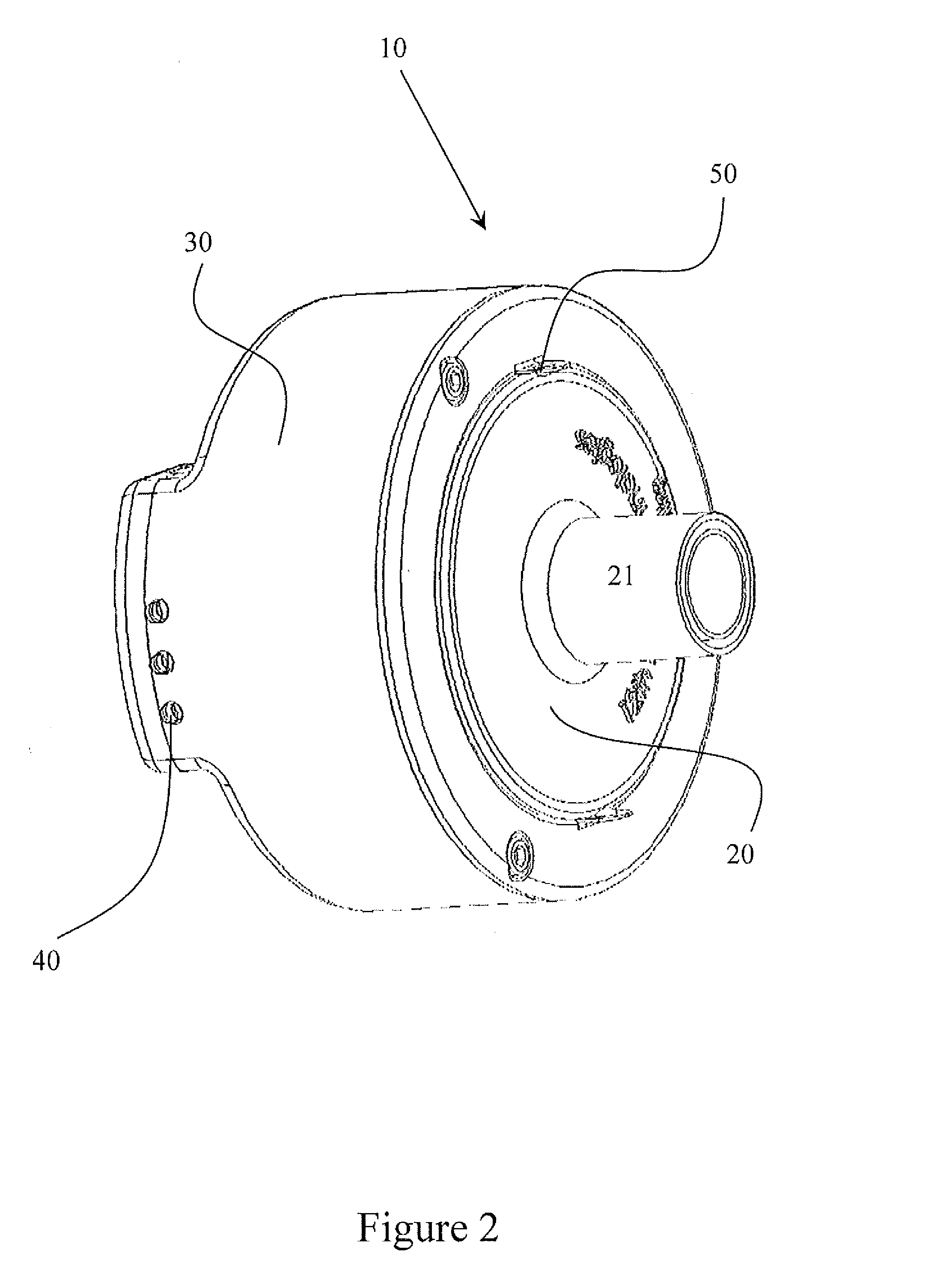
The present invention is a filter that can remove harmful substances from a gas while keeping moisture in a vapor phase. The filter has a housing with two openings, a filter medium inside the housing, and a mechanical extension that can close an electrical switch. The filter can be used in a heating chamber and is designed to fit there. It can also be heated when the mechanical extension engages a recessed electrical switch. The mechanical extension can be a ring or plastic. The filter can be a HEPA filter or a bacterial filter for a ventilator. The gas can be an exhaled gas from a ventilated subject.

Problems solved by technology

The technical problem addressed in this patent text is the need for a heated filter and filtration system that can effectively control the heating element based on the presence of the filter, without creating a potential risk to operators. Existing heated filters have separate control mechanisms, which may not always be effective. The present invention provides a solution to this problem.

Method used


Image

  • Bacteria Filter and Heating System
  • Bacteria Filter and Heating System
  • Bacteria Filter and Heating System

Examples


Embodiment Construction

[0016]It is to be understood that the figures and descriptions of the present invention have been simplified to illustrate elements that are relevant for a clear understanding of the present invention, while eliminating, for the purpose of clarity, many other elements found in heated filter systems and methods. Those of ordinary skill in the art may recognize that other elements and / or steps are desirable and / or required in implementing the present invention. However, because such elements and steps are well known in the art, and because they do not facilitate a better understanding of the present invention, a discussion of such elements and steps is not provided herein. The disclosure herein is directed to all such variations and modifications to such elements and methods known to those skilled in the art.

[0017]Unless defined otherwise, all technical and scientific terms used herein have the same meaning as commonly understood by one of ordinary skill in the art to which this inven...


PUM


Abstract

A system for keeping moisture in a vapor phase and for removing particles from a gas is described. The system includes a filter and a heating chamber. The filter is capable of being heated and includes a mechanical element that effectively regulates the heating of the filter. Heat production of the heating chamber is coupled to the proper insertion of the filter into the chamber, such that the filter closes an electrical switch in the heating chamber to allow for the production of heat. An exemplary use of the system is the keeping moisture in a vapor phase and removing pathogenic particles from the exhalation path of a ventilated subject.

Description


Claims


Application Information

Patent Timeline
Owner 12TH MAN TECH
Learn More