Flange protector and masking device

Inactive Publication Date: 2013-06-20
PROTECTIVE INDS
View PDF11 Cites 5 Cited by
  • Summary
  • Abstract
  • Description
  • Claims
  • Application Information

AI Technical Summary

Benefits of technology

The present invention is a reusable flange protector that can protect the raised surface of a flange during sand blasting, painting, or plating. The protector is made of flexible material that is resistant to impact and weather conditions. It has a cover portion that can cover the raised face of the flange, and a skirt that extends from the cover portion. The skirt has tabs for easy attachment to the flange. The protector can be easily stored when not in use. In combination with a flange, the protector provides protection for the raised surface of the flange.

Problems solved by technology

As operating pressures in the piping systems where flanges are used can exceed 2,500 PSI, any type of damage to the flange sealing surface (nicks, scratches, dings, etc.) can create significant maintenance and safety issues.
For instance, it is at times difficult to install the flange protector, particularly when the flange protector has lugs which must be seated within bolt holes spaced about the periphery of a flange to be protected.
Depending upon the flexibility of the flange protector body, it may be difficult to engage a number of lugs within multiple bolt holes at the same time.
The use of adhesives may be less than effective due to the potential effect of the environment during storage and transport.
The use of bolts to attach the die-cut flange protector is labor intensive from the standpoint of attachment and removal.
The use of whole-flange covers requires the use of a multitude of sizes, and such covers are ineffective as masking devices.
Additionally, injection molded designs typically contain molded-in stresses, and warping frequently prevents the protector from laying flat against the raised sealing face of the valve or flange.
This condition creates gaps between the protector and the raised face making the surface more prone to damage, and additionally making installation and removal more difficult.
It may also be difficult to remove the flange protector once installed on the flange when lugs are used, as the flange protector is maintained in place by the action of multiple lugs which are each snugly fit within a bolt hole.
The removal of the lugs is made more difficult due to the fact that a number of lugs must be removed at the same time, as well as the fact that the lugs must each be lifted from the bolt holes in the direction of the longitudinal axis of the bolt holes in order to be removed.
Such removal is also made difficult by the fact that the flange protector is relatively inflexible, since the material employed must be impact-resistant in order to provide adequate protection.

Method used


Image

  • Flange protector and masking device
  • Flange protector and masking device
  • Flange protector and masking device

Examples


Embodiment Construction

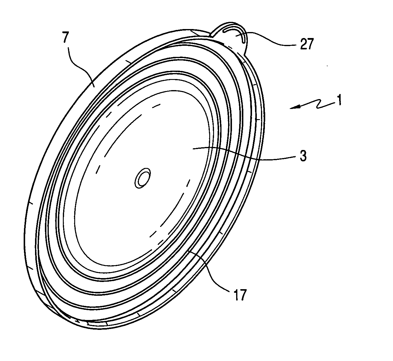
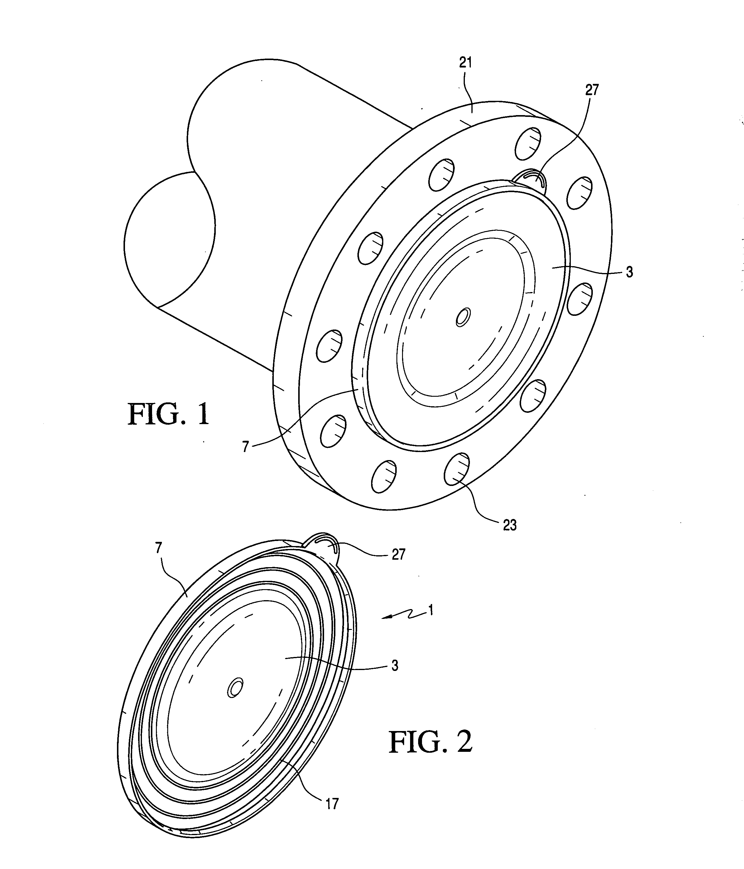
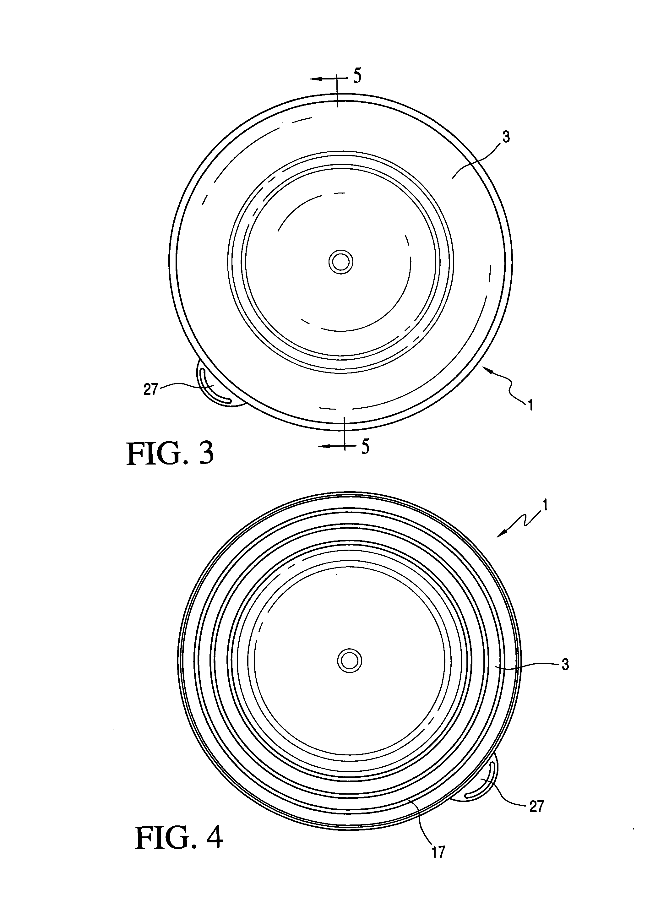
[0037]The flange protector of the present invention will be described in connection with FIGS. 1-18.

[0038]The flange protector 1 of the present invention comprises a generally planar cover 3 having the configuration of a flange facing surface 5 to be protected, and including a skirt portion 7 extending from a circumferential edge thereof and configured to engage a shoulder portion 9 of the flange 21 which defines the circumferential extent of the raised flange face 1. The cover portion 3 of the flange protector will correspond to the configuration of the raised flange face 5 to ensure full protection, and will accordingly generally be circular in configuration, as this is generally the configuration of the flange surface to be protected.

[0039]The skirt portion 7 extends from the periphery of the cover portion 3 and is of such length as to extend along at least a portion of the shoulder portion 9 to maintain the cover portion 3 in registry with the face of the flange.

[0040]While the ...


PUM


Abstract

A flange protector is provided for a raised face of a flange comprising a flexible impact-resistant material having a cover portion, the raised surface defined by a circumferential raised shoulder portion extending from a surface of the flange, the cover portion having such dimension and configured to cover in protective relationship the raised surface of a flange, the flange protector extending across the raised surface and having a skirt portion which extends downwardly in encompassing relationship to the shoulder portion from the flange surface, the skirt portion contacting the raised shoulder portion at a single point of contact.

Description

BACKGROUND OF THE PRESENT INVENTION[0001]The present invention is directed to a flange protector and masking device for use with a flange which may be used, for instance, for making connections to pipes, valves, etc. Such flanges have bolt holes adapted to receive bolts for making such connections to a mating flange having corresponding bolt holes.[0002]The flange face surface will typically be finely machined to ensure a tight seal between the mating flange surfaces and an intervening sealing gasket that is compressed between the opposing flange surfaces when connected together with bolts via the bolt holes in the opposing flanges. As operating pressures in the piping systems where flanges are used can exceed 2,500 PSI, any type of damage to the flange sealing surface (nicks, scratches, dings, etc.) can create significant maintenance and safety issues. The use of a flange protector during storage, shipment, etc. is thus found useful to protect the flange face surface as a cost avoi...

Claims


Application Information

Patent Timeline
IPC IPC(8): B65D59/06
CPCF16L57/005
Inventor ZEYFANG, FREDERICK W.SARDINI, WILLIAM H.
Owner PROTECTIVE INDS
Why Eureka
Try Eureka