Coil component

a technology of coils and components, applied in the direction of transformers/inductance details, inductances, inductances with magnetic cores, etc., can solve the problems of lowering reducing so as to increase the bending accuracy and heighten the bending accuracy of the terminal

Active Publication Date: 2013-06-20
SUMIDA CORP
View PDF6 Cites 12 Cited by
  • Summary
  • Abstract
  • Description
  • Claims
  • Application Information

AI Technical Summary

Benefits of technology

[0012]According to the coil component of the present invention, it is possible to bend the flat-shaped terminal by a small force, so that it is possible to heighten the bending accuracy and it is possible to bend the flat-shaped terminal accurately along the corner between the side surface and the bottom surface of the magnetic core. As a result thereof, it is possible to heighten the bending accuracy of the terminal, so that it is possible to provide a coil component in which the external-dimensional accuracy is preferable.

Problems solved by technology

Then, an excessive force was necessary for bending the flat-shaped terminal approximately as much as 90 degree. Therefore, the adjustment of the force to be added to the terminal when bending was difficult and there occurs a situation in which the bending accuracy of the terminal lowered.
As a result thereof, in a case in which the force when bending the terminal is large, there was a fear that the corner of the magnetic core may be damaged by the force when bending the terminal.

Method used


Image

  • Coil component
  • Coil component
  • Coil component

Examples


first exemplified embodiment

1. First Exemplified Embodiment

1-1. Constitution of Coil Component

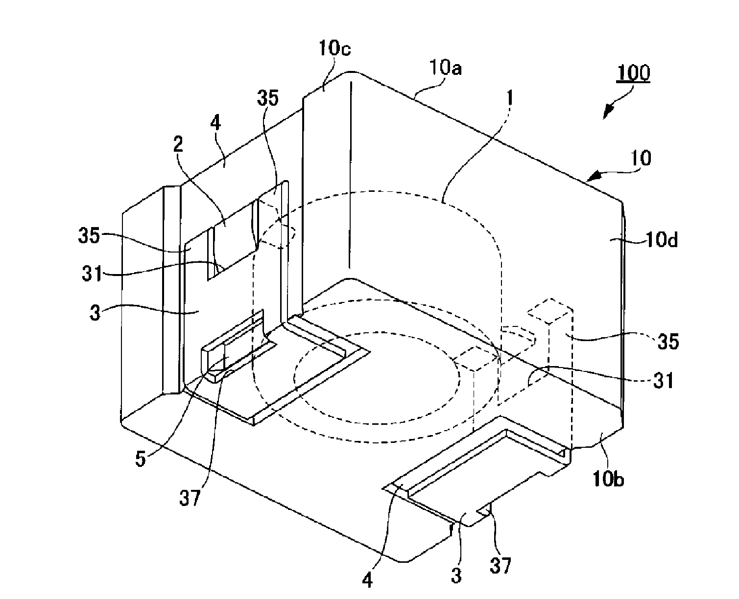
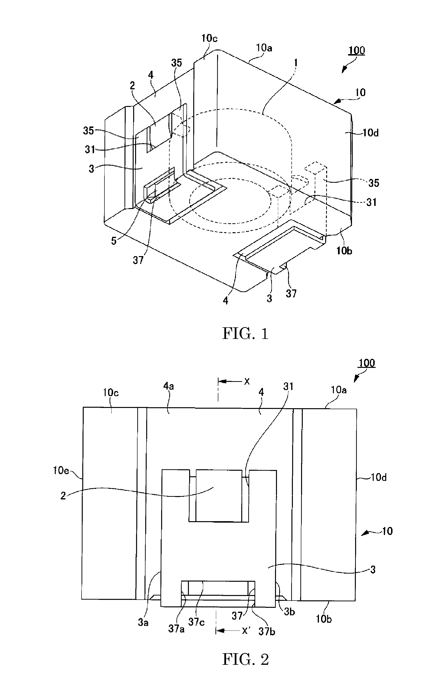
[0032]First, by using FIGS. 1 to 4, there will be explained a constitution of a coil component relating to a first exemplified embodiment (hereinafter, referred to as “this embodiment”) of the present invention.

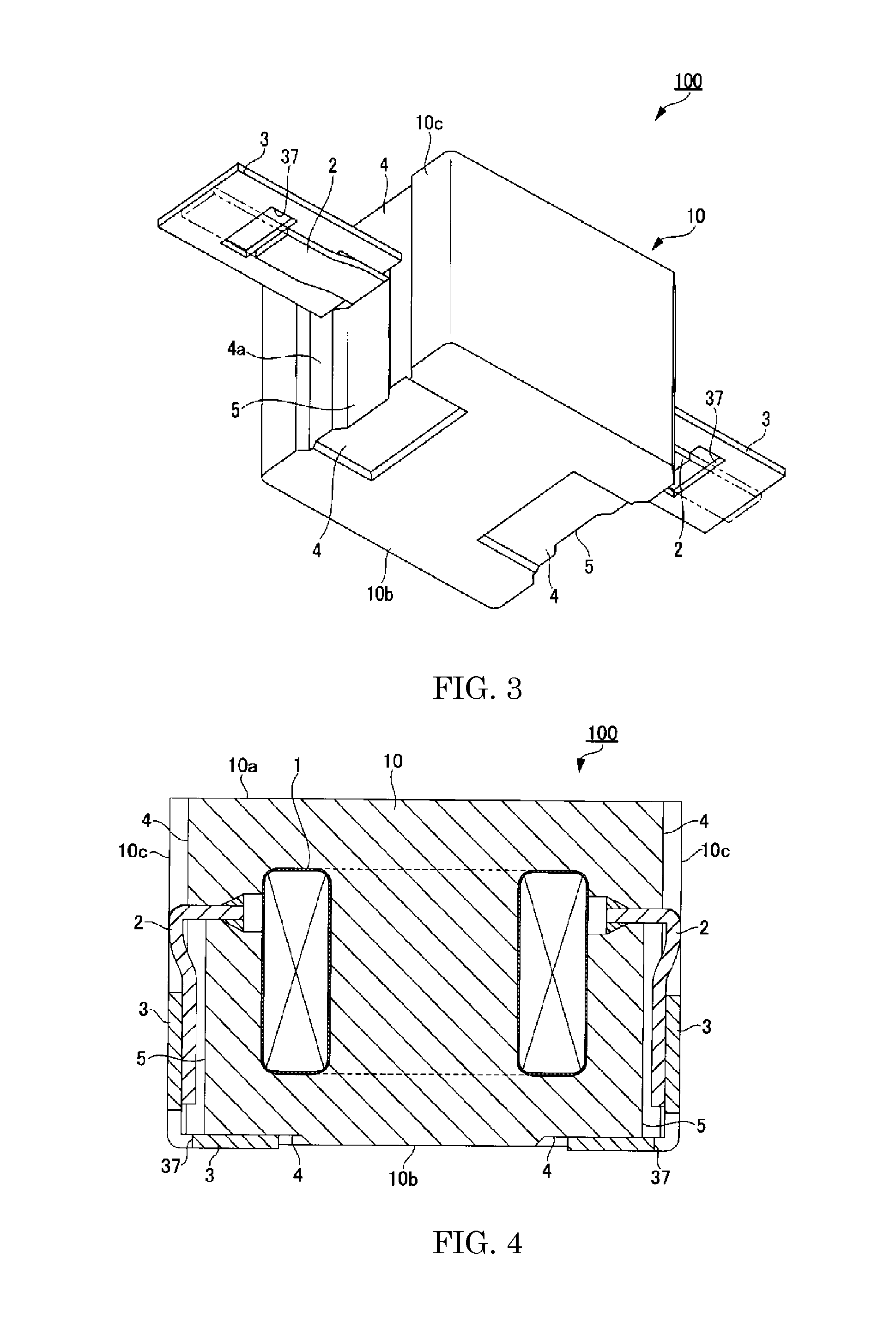
[0033]FIG. 1 is a perspective view of a coil component of this embodiment. Also, FIG. 2 is a side view of the coil component of this embodiment, and FIG. 3 is a perspective view showing a state before bending a flat-shaped terminal in the coil component. FIG. 4 is a cross-sectional view at an X-X′ line in FIG. 2.

[0034]A coil component 100 of this embodiment is a component used for an automobile, various kinds of electrical products, electronic equipments or the like. As shown in FIG. 1, the coil component 100 is provided, for example, with a magnetic core 10 composed of a magnetic material, a coil 1, and two terminals 3 connected to coil end portions 2 of the coil 1.

[0035]There is no limitation in particular he...

second exemplified embodiment

2. Second Exemplified Embodiment

[0075]Next, there will be explained a coil component relating to a second exemplified embodiment of the present invention with reference to FIG. 5 and FIG. 6.

[0076]FIG. 5 is a perspective view showing a constitution of a coil component 200 relating to the second exemplified embodiment and FIG. 6 is a side view showing the coil component. It should be noted that the same reference numerals are applied for the portions corresponding to those in the first exemplified embodiment (FIGS. 1 to 4), in which repetitive explanations thereof are to be avoided.

[0077]As shown in FIG. 5 and FIG. 6, the coil component 200 relating to the second exemplified embodiment is a component in which the opening portions 37 provided at the terminals 3 are filled with filling members 41. These filling members 41 are members with which the opening portions 37 are filled after bending the terminals 3 from the side surfaces 10c to the bottom surface 10b of the magnetic core 10.

[0...

third exemplified embodiment

3. Third Exemplified Embodiment

[0082]Next, there will be explained a coil component relating to a third exemplified embodiment of the present invention with reference to FIG. 7 and FIG. 8.

[0083]FIG. 7 is a perspective view showing a coil component 300 relating to the third exemplified embodiment and FIG. 8 is a perspective view showing a state before bending the terminals 3 in the coil component 300.

[0084]The aspects, in which the coil component 300 relating to this third exemplified embodiment is different from the coil component 100 relating to the first exemplified embodiment, lie in the positions at which the coil end portions of the coil are cut and the shape of the magnetic core. Therefore, here, there will be explained the coil end portions and the magnetic core, in which the same reference numerals are applied to the portions common to those of the coil component 100 and repetitive explanations thereof will be omitted.

[0085]As shown in FIG. 7, the coil component 300 is provi...


PUM

PropertyMeasurementUnit
melting pointaaaaaaaaaa
rectangular shapeaaaaaaaaaa
widthaaaaaaaaaa

Abstract

A coil component including: a magnetic core which is formed by a magnetic material and which has a top surface, a bottom surface facing the top surface and a side surface continuous approximately perpendicularly to the top surface and the bottom surface; a coil which is buried inside the magnetic core and whose end portion protrudes from the side surface of the magnetic core; a flat-shaped terminal which protrudes from the side surface of the magnetic core, is bent toward the bottom surface of the magnetic core and is connected with the end portion of the coil, wherein there is formed an opening portion at a position corresponding to the place which is bent for the flat-shaped terminal from the side surface to the bottom surface of the magnetic core.

Description

CROSS REFERENCE TO RELATED APPLICATION[0001]The present invention contains subject matter related to Japanese Patent Application 2011-274495 filed in the Japanese Patent Office on Dec. 15, 2011, the entire contents of which being incorporated herein by reference.BACKGROUND OF THE INVENTION[0002]1. Field of the Invention[0003]The present invention relates to a coil component which is used for various kinds of electrical products, electronic equipment or the like.[0004]2. Description of the Related Art[0005]For the coil component in the past, there exists a coil component in which a coil formed by winding a conductive wire is buried inside a magnetic core formed by a magnetic material, such as described, for example, in Patent Document 1 (Japanese unexamined patent publication No. 2005-310869). In this coil component, the coil is buried inside the magnetic core and the lead line of the coil, so called the end portion, protrudes from the side surface of the coil component.[0006]Also, t...

Claims


Application Information

Patent Timeline
Patent Type & Authority Applications(United States)
IPC IPC(8): H01F27/29
CPCH01F17/043H01F27/29H01F27/292
Inventor YAMADA, SATORUKIKUCHI, KAZUYUKITAHARA, YOSHIYUKI
Owner SUMIDA CORP
Why Eureka
Try Eureka