Connecting rod type bending device used for reinforcement forming machine to bend reinforcement

A technology for bending steel bars and a bending device is applied in the field of connecting rod bending devices, which can solve the problems of low work efficiency and high labor intensity, and achieve the effects of simple structure, improved work efficiency and wide application range.

Active Publication Date: 2014-12-24
湖州佳灏信息技术有限公司
View PDF6 Cites 6 Cited by
  • Summary
  • Abstract
  • Description
  • Claims
  • Application Information

AI Technical Summary

Problems solved by technology

[0002] Various steel bars are often used in construction projects. The stirrup is also a kind of steel bar. It is mainly used to fix the position of the main steel bar and make the various steel bars inside the building components form a steel skeleton. The stirrups used in construction have various shapes. It is widely used, and the most common one is the stirrup skeleton frame that is bent into a rectangle by straight steel bars. The stirrup skeleton frame has five corners. Usually, two corners need to be bent first, and then turned around. For the two corners at the other end, the last corner is manually bent in the middle of the steel bar, and a total of five bending processes are performed to bend the steel bar into a rectangular frame to obtain a stirrup skeleton frame, which is labor-intensive and low-efficiency

Method used


Image

  • Connecting rod type bending device used for reinforcement forming machine to bend reinforcement
  • Connecting rod type bending device used for reinforcement forming machine to bend reinforcement
  • Connecting rod type bending device used for reinforcement forming machine to bend reinforcement

Examples


Embodiment Construction

[0017] In order to make the objects and advantages of the present invention more clear, the present invention will be further described in detail below with reference to the embodiments. It should be understood that the specific embodiments described herein are only used to explain the present invention, but not to limit the present invention.

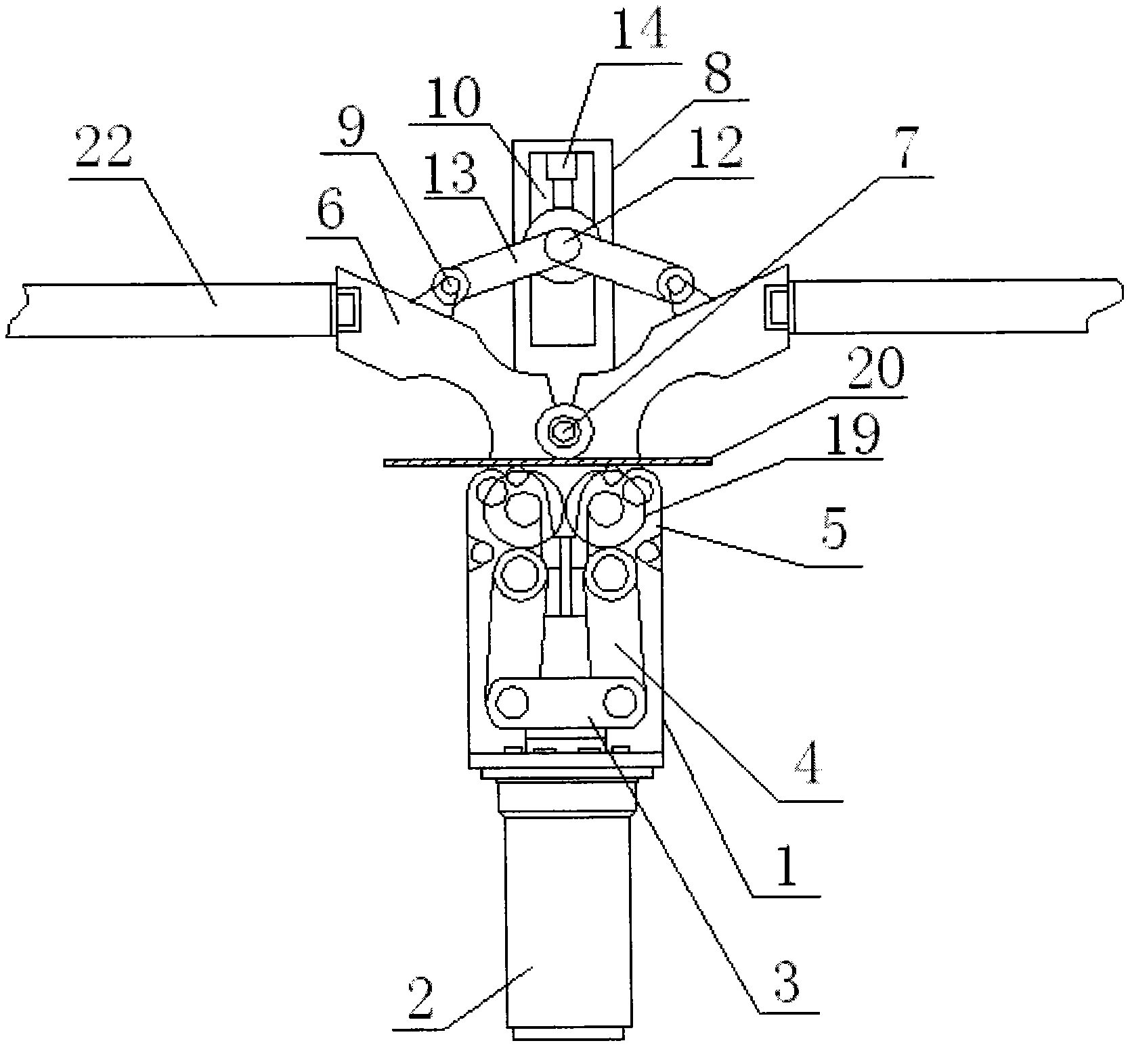
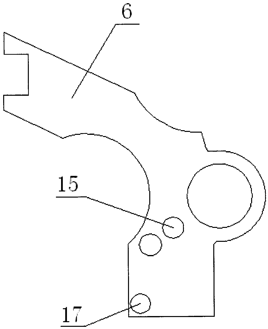
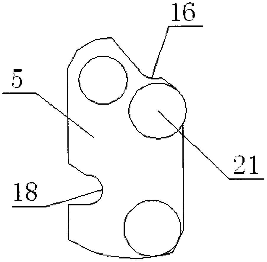
[0018] like Figure 1-4 As shown, the embodiment of the present invention provides a connecting rod type bending device for bending steel bars by a steel bar forming machine, comprising a base 1, an oil cylinder 2 arranged on the base 1, and an oil cylinder 2 arranged on the base 1 The push rod 3, the connecting rod 4 set on the base 1, the pin thrust seat 5 set on the base 1, the hinge plate 6 set on the base 1, and the hinge plate 6 set on the base 1 The hinge pin 7, and the fixed plate 8 arranged above the base 1, the hinge plate 6 is provided with a fixed hinge 9, the fixed plate 8 is provided with a chute 10, and the chute 10 is ...


PUM


Abstract

The invention discloses a connecting rod type bending device used for a reinforcement forming machine to bend a reinforcement. The connecting rod type bending device comprises a base, an oil cylinder, a push rod, a connecting rod, a hinge pin thrust bearing, a hinged plate, an articulated hinge pin and a fixed plate, wherein the oil cylinder is arranged on the base; the push rod is arranged on the base; the connecting rod is arranged on the base; the hinge pin thrust bearing is arranged on the base; the hinged plate is arranged on the base; the articulated hinge pin is arranged on the base; the fixed plate is arranged above the base; a fixed hinge is arranged on the hinged plate; the fixed plate is provided with a chute; a sliding block is arranged in the chute; a movable hinge is arranged on the sliding block; a connecting rod is arranged on the movable hinge; the connecting rod is connected with the fixed hinge; a hydraulic rod is arranged in the chute; the hydraulic rod is connected with the sliding block; the push rod is connected with the oil cylinder; an inner limiting pin for limiting an internal rotation distance of the hinge pin thrust bearing is arranged on the hinged plate; an outer limiting pin for limiting an external rotation distance of the hinge pin thrust bearing is arranged on the hinged plate.

Description

technical field [0001] The invention relates to a connecting rod type bending device used for bending steel bars by a steel bar forming machine. Background technique [0002] Various steel bars are often used in construction projects, and stirrups are also a kind of steel bars. They are mainly used to fix the position of the main steel bars and make various steel bars inside the building components form a steel skeleton. The stirrups used in construction have various shapes. It has a wide range of applications. The most common one is the stirrup skeleton frame that is bent from straight steel bars into a rectangle. The stirrup skeleton frame has five corners. Usually, two corners need to be bent first, and then turned around and bent. At the other end of the two corners, the last corner is manually bent in the middle of the steel bar, and a total of five bending processes are performed to bend the steel bar into a rectangular frame to obtain a stirrup skeleton frame, which h...

Claims


Application Information

Patent Timeline
Patent Type & Authority Applications(China)
IPC IPC(8): B21F1/00
Inventor 郑旭
Owner 湖州佳灏信息技术有限公司
Why Eureka
Try Eureka