Pipe bending machine

A pipe bender and pipe bending technology, applied in the field of pipe benders, can solve problems such as high system cost, poor reliability, and pipe deviation, and achieve the effect of high bending precision and low cost

Pending Publication Date: 2018-08-03
佛山市佳锐智能装备有限公司
View PDF0 Cites 6 Cited by
  • Summary
  • Abstract
  • Description
  • Claims
  • Application Information

AI Technical Summary

Problems solved by technology

However, the forming die of the forming mechanism of the existing pipe bending machine is connected with a hydraulic drive device to drive it to rotate, and the hydraulic drive device has the disadvantages of high system cost, poor reliability, troublesome maintenance and pressure maintenance; and because the bend pipe is installed on the forming die Between the output mechanism of the bent pipe and the large span, it is easy to cause the pipe to deviate

Method used


Image

  • Pipe bending machine
  • Pipe bending machine
  • Pipe bending machine

Examples


Embodiment Construction

[0030] The present invention will be further described below in conjunction with the accompanying drawings and embodiments.

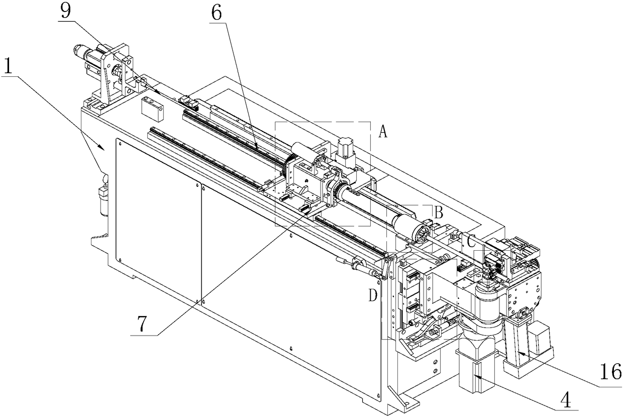
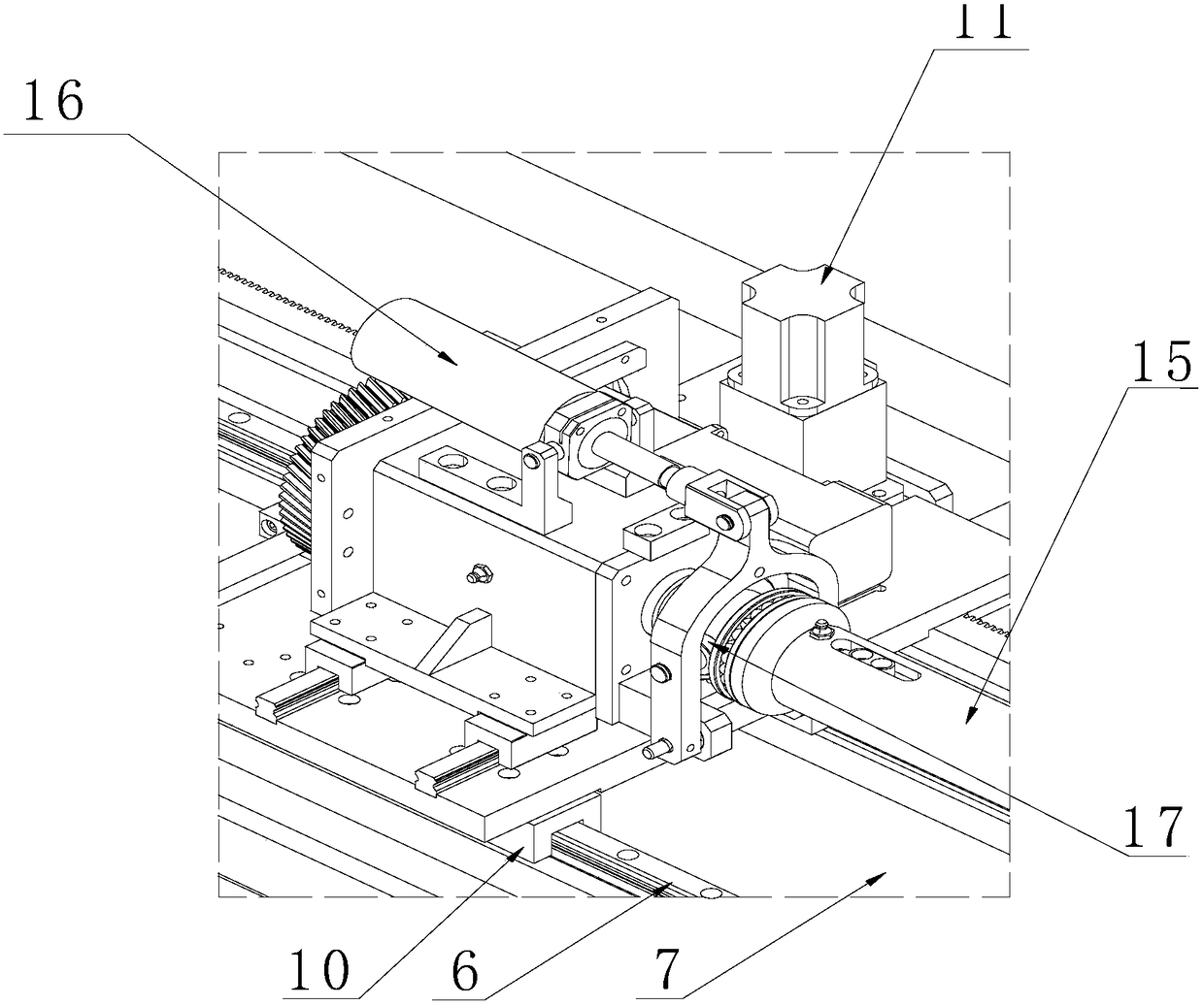
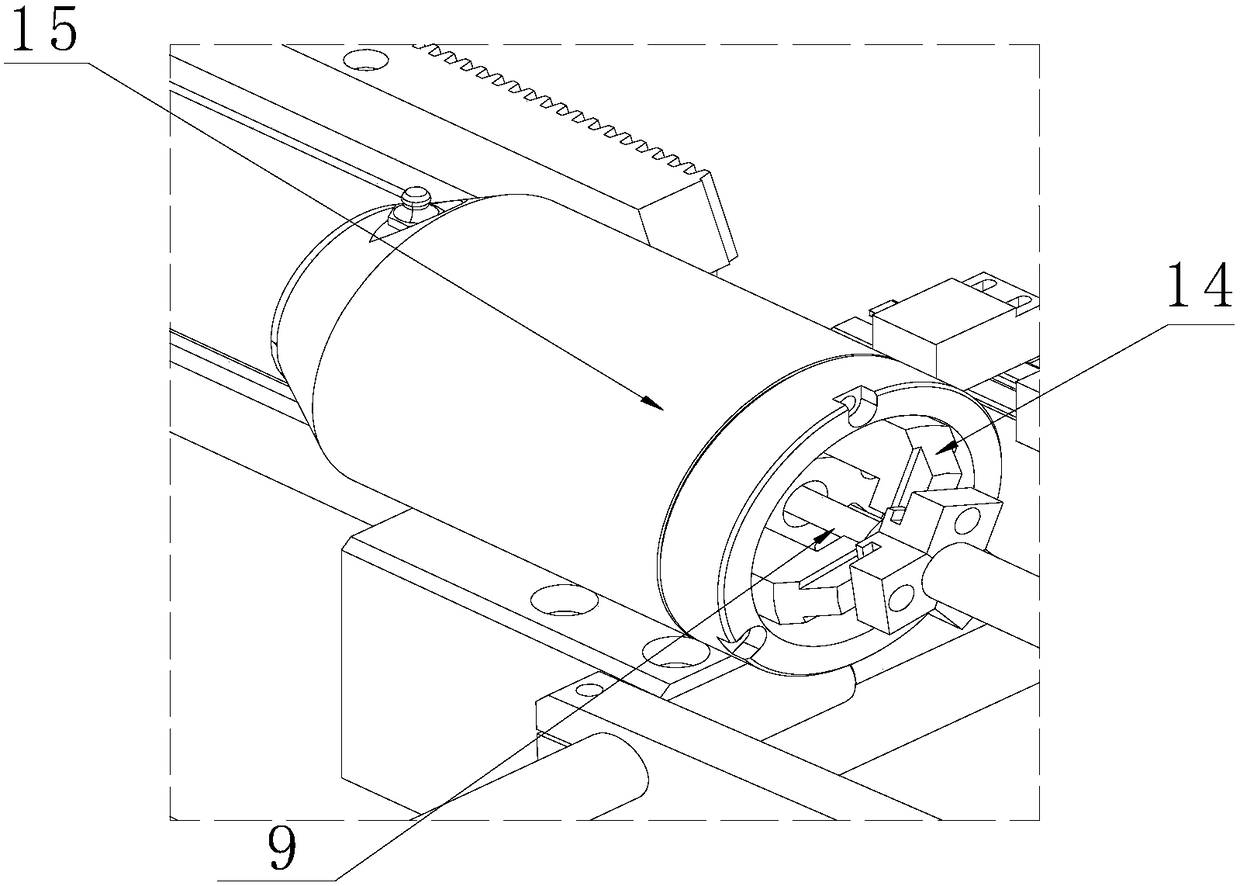
[0031] Such as Figure 1-12 A pipe bending machine shown includes a frame 1, a pipe bending output mechanism arranged on the frame 1, and a pipe bending forming mechanism arranged on one side of the pipe bending output mechanism; the pipe bending forming mold includes 2 cooperating Wheel mold 3 and clamping mold 2, two wheel molds 3 and two clamping molds 2 are superimposed vertical design, that is, an upper cavity and a lower cavity are formed; wheel mold 3 and clamping mold 2 rotate synchronously; clamping mold 2 is connected There is a servo electric cylinder 16 that drives it to clamp with the wheel mold 3; the servo electric cylinder 16 rotates synchronously with the clamping mold 2; the wheel mold 3 and the clamping mold 2 are molded together and form a cavity for extruding the deformation of the pipe; the clamping mold 2 Connected with the first...


PUM


Abstract

The invention discloses a pipe bending machine which comprises a frame, a pipe bending outputting mechanism and a pipe bending molding mechanism, wherein the pipe bending outputting mechanism is arranged on the frame; and the pipe bending molding mechanism is arranged on one side of the pipe bending outputting mechanism, comprises a pipe bending molding die for holding a to-be-processed pipe, andis characterized in that the pipe bending molding die comprises a plurality of vertical bending dies and clamping dies, which are overlapped; each clamping die is connected with a servo electric cylinder; and cavities are formed by closing the bending dies and the clamping dies; the pipe bending molding die is characterized in that the clamping dies are connected with first driving motors for driving the clamping dies to rotate; a supporting assembly used for supporting the to-be-processed pipe is arranged on the frame, and comprises a supporting block for supporting the to-be-processed pipe and a driving device for switching the working states of the supporting block; the output end of the driving device is connected with the supporting block; and a supporting position used for supportingthe to-be-processed pipe is arranged on the supporting block. The pipe bending machine has the advantages of being high in bending precision, low in cost, high in reliability and having no hydraulicoil pollution.

Description

technical field [0001] The invention relates to the field of processing machinery for automobiles and decorative accessories, in particular to a pipe bending machine. Background technique [0002] Many automobiles or decorative accessories use steel pipe brackets of various shapes, and these steel pipe brackets of various shapes need to be bent and formed by bending machines. However, the forming die of the forming mechanism of the existing pipe bending machine is connected with a hydraulic drive device to drive it to rotate, and the hydraulic drive device has the disadvantages of high system cost, poor reliability, troublesome maintenance and pressure maintenance; and because the bend pipe is installed on the forming die There is a large span between the pipe and the output mechanism of the elbow, which may easily cause the pipe to deviate. [0003] Therefore, it is necessary to develop a new type of pipe bending machine to solve the above problems. Contents of the inven...

Claims


Application Information

Patent Timeline
Patent Type & Authority Applications(China)
IPC IPC(8): B21D7/08
CPCB21D7/085
Inventor 吴建波彭祥耀
Owner 佛山市佳锐智能装备有限公司
Why Eureka
Try Eureka