
Display device and electronic device

a technology of electronic devices and display devices, applied in static indicating devices, instruments, non-linear optics, etc., can solve the problems of color shift problem at different viewing, serious dispersion problem of conventional bplc display,

Inactive Publication Date: 2013-06-20
INNOCOM TECH SHENZHEN +1
View PDF3 Cites 38 Cited by
  • Summary
  • Abstract
  • Description
  • Claims
  • Application Information

AI Technical Summary

Benefits of technology

The patent describes a display device that allows for the transmission of light of different wavelengths through different sub-pixels. The device includes interdigitated electrodes with specific ratios to ensure optimal performance. The device also has different cell gaps for each sub-pixel to improve image quality. The technical effects of this design include improved color accuracy, reduced power consumption, and improved image quality.

Problems solved by technology

Thus, the conventional BPLC display has a serious dispersion problem.
Also, the conventional BPLC display has a color shift problem at different viewing-angles.

Method used


Image

  • Display device and electronic device
  • Display device and electronic device
  • Display device and electronic device

Examples


Embodiment Construction

[0033]The following description is of a mode for carrying out the invention. This description is made for the purpose of illustrating the general principles of the invention and should not be taken in a limiting sense. The scope of the invention is best determined by reference to the appended claims. Wherever possible, the same reference numbers are used in the drawings and the descriptions to refer the same or like parts.

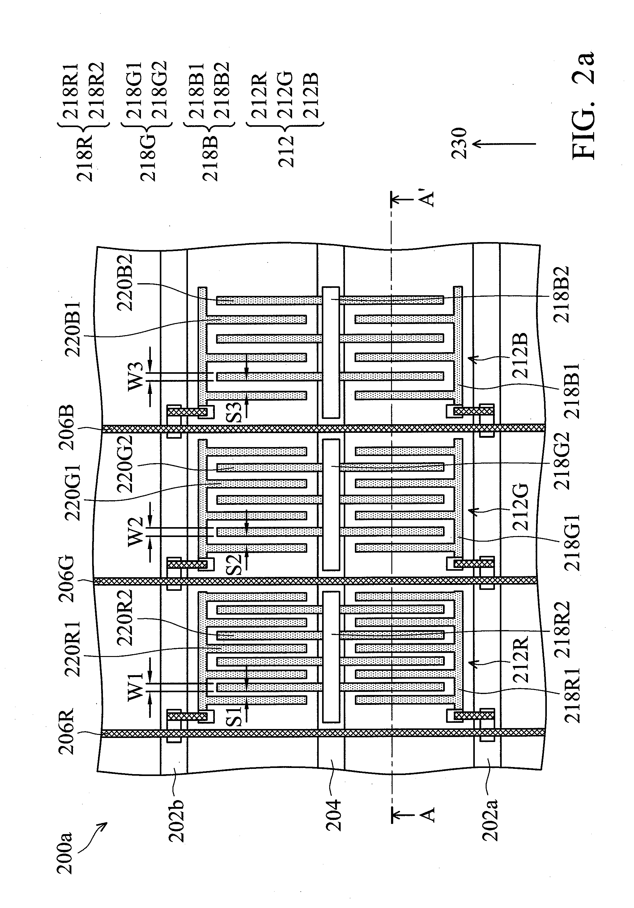
[0034]FIGS. 2a and 2b are respectively a top view and a cross sectional view taken along line A-A′ of FIG. 2a showing one exemplary embodiment of a pixel area 212 of a display device 200a of the invention. One exemplary embodiment of a display device 200a is a blue phase liquid crystal (BPLC) display device designed by the wide viewing-angle in-plane switching (IPS) technology. A second substrate (opposite substrate) and a blue phase liquid crystal (BPLC) layer are omitted in the top view of the pixel area 212 of the display device 200a (FIG. 2a) for brevity. As sh...


PUM


Abstract

A display device includes a first, second and third sub-pixel areas allowing light of a first, second and third main wavelengths transmitting therethrough, respectively. The first, second and third sub-pixel areas have first, second and third ratios of first, second and third electrode widths to first, second and third electrode slits of first, second and third interdigitated electrodes, respectively. When the first main wavelength is larger than the second main wavelength and the second main wavelength is larger than the third main wavelength, a difference between any two of the first, second and third ratios is less than 0.2. A first electrode slit of the first interdigitated electrode is smaller than the second electrode slit of the second interdigitated electrode, and the second electrode slit of the second interdigitated electrode is smaller than the third electrode slit of the third interdigitated electrode.

Description

CROSS REFERENCE TO RELATED APPLICATIONS[0001]This application claims priority of Taiwan Patent Application No. 100147279, filed on Dec. 20, 2011, the entirety of which is incorporated by reference herein.BACKGROUND OF THE INVENTION[0002]1. Field of the Invention[0003]The present invention relates to a display device, and in particular, to a display device with low dispersion.[0004]2. Description of the Related Art[0005]A blue phase liquid crystal (BPLC) has advantages of having a fast response time, and being free of an alignment layer. Also, the BPLC is optically isotropic. Therefore, the BPLC shows an ideal dark state.[0006]Birefringence dispersion (Δn) of the conventional LC is expressed by using the Cauchy dispersion formula (Formula (1))Δn~3GS2λ2λ*2λ2-λ*2,formula(1)wherein G is proportionality constant, S is order parameter and λ* is mean resonance wavelength.[0007]Macroscopically, birefringence dispersion (Δn) of the BPLC is expressed by using the Kerr effect formula (Formula ...

Claims


Application Information

Patent Timeline
IPC IPC(8): G02F1/1343G09G3/36
CPCG02F1/134336G09G3/36G02F2001/13793G02F1/134363G02F1/133371G02F1/13793
Inventor CHEN, CHIEN-HUNGCHEN, YU-WEI
Owner INNOCOM TECH SHENZHEN
Learn More