Radiation tomography apparatus

Inactive Publication Date: 2013-06-20
SHIMADZU CORP
View PDF5 Cites 2 Cited by
  • Summary
  • Abstract
  • Description
  • Claims
  • Application Information

AI Technical Summary

Benefits of technology

[0012]This invention includes the first cylinder having the opening for introducing the support member, the first positioning device for positioning the first cylinder, and the support member guided in the first cylinder for supporting the subject movable relative to the first cylinder. Such configuration causes the support member to support while guide the subject. Accordingly, the subject during the movement always has a constant position in the vertical direction. In other words, according to the configuration of this invention, no deviation in position of the subject occurs during radiography and thus tomography images can be provided with high visibility and no distortion.
[0013]Moreover, the first cylinder also serves to prevent the subject from escaping into the apparatus or to prevent excrement of the subject from entering into the apparatus. Consequently, this invention can provide a radiation tomography apparatus with less failure.
[0014]The aforementioned radiation tomography apparatus further includes a second imaging device provided adjacent to the first imaging device in the introduction direction for taking tomography images of the subject by introducing the subject in the introduction direction; a second cylinder provided in a second imaging view field of the second imaging device and having an opening extending in the introduction direction for introducing the support member; and a second positioning device for positioning the second cylinder relative to the second ima

Problems solved by technology

The conventional construction, however, has the following problem.
Specifically, the problem arises that the conventional configuration has difficulty in moving the subject accurately.
The subject has a length longer than an imaging view field of the appara

Method used


Image

  • Radiation tomography apparatus
  • Radiation tomography apparatus
  • Radiation tomography apparatus

Examples


Example

Example 1

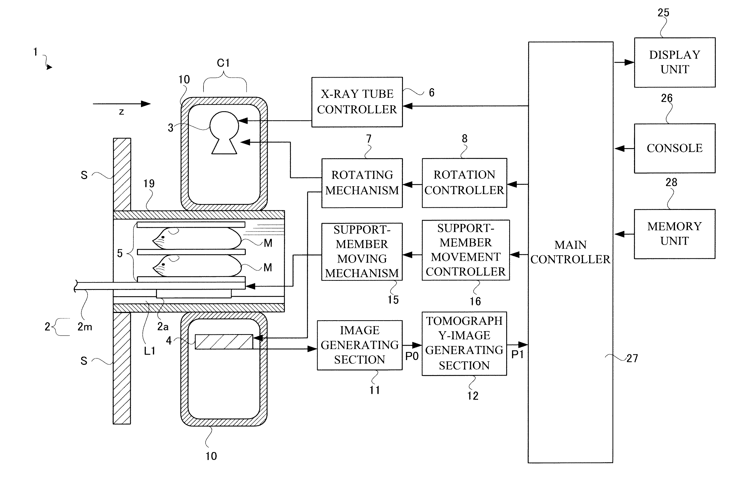
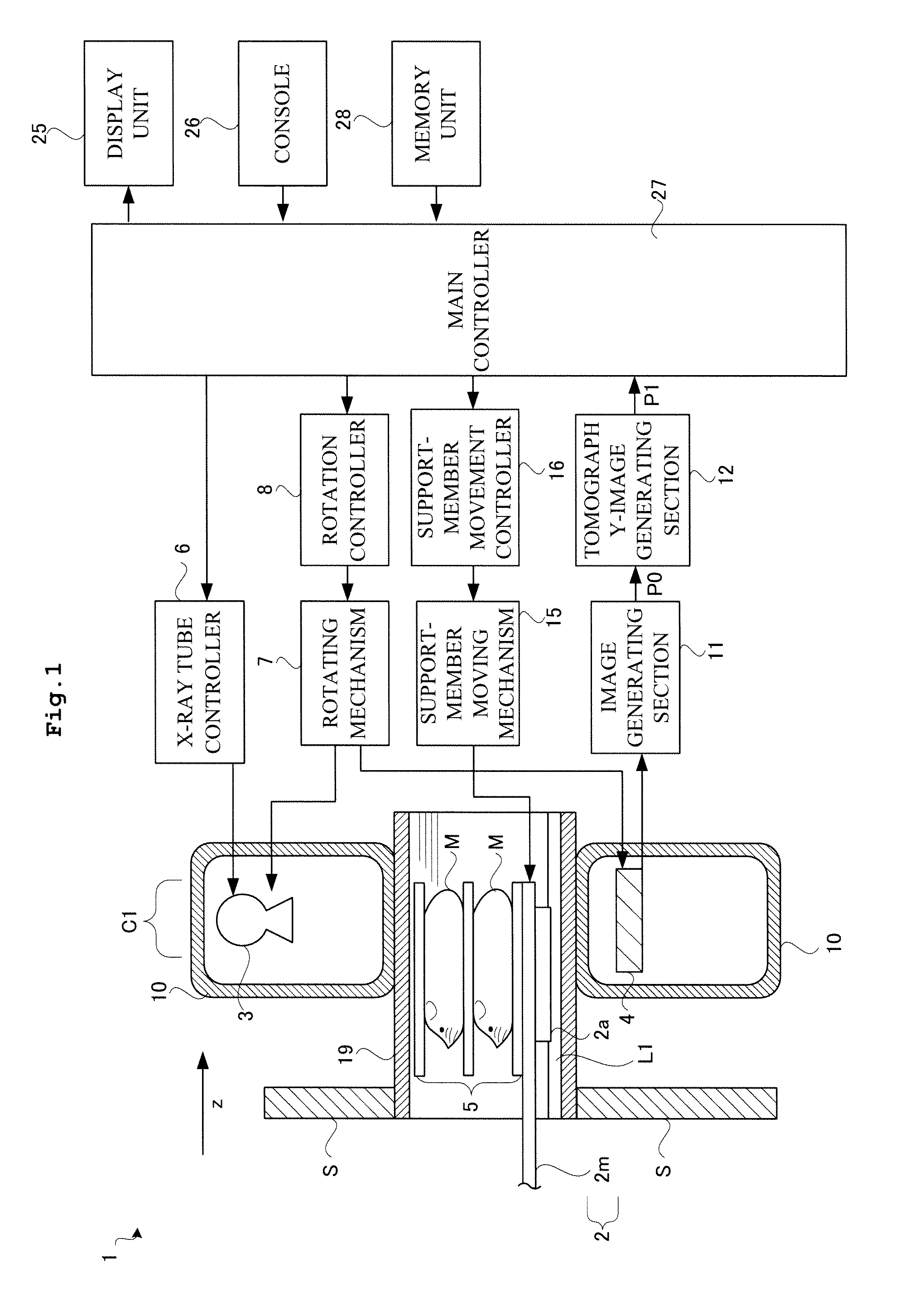
[0046]Description will be given first of a tomographic X-ray apparatus according to Example 1. As shown in FIG. 1, a fluoroscopic X-ray apparatus 1 includes a support member 2 for supporting a subject M placed thereon, and a gantry 10 with a through hole in a direction where the support member 2 extends. The support member 2 is inserted into the through hole of the gantry 10. The support member 2 can move forward and backward in the direction where the support member 2 extends (i.e., an orthogonal direction of an imaginary circle VC to be mentioned later: a z-direction) relative to a support board S. The support member 2 is moved by a support-member moving mechanism 15. The support-member moving mechanism 15 is controlled by a support-member movement controller 16. Here, the support-member moving mechanism 15 corresponds to the support-member moving device in this invention. The support-member movement controller 16 corresponds to the support-member movement control device ...

Example

Example 2

[0080]Next, description will be given of a tomography apparatus 21 according to Example 2. The tomography apparatus 21 according to Example 2 includes a positron emission tomography device (PET device) in addition to the apparatus configuration of Example 1, as shown in FIG. 11. Here, in the tomography apparatus 21 according to Example 2, explanation is to be omitted to the same elements as those in the apparatus configuration of Example 1.

[0081]The tomography apparatus 21 includes a gantry 10a concerning a PET device 1a besides the gantry 10. The gantry 10a also has a through hole extending in the z-direction into which the support member 2 is inserted. Accordingly, the PET device 1a is provided adjacent to the X-ray tube 3 and the FPD 4 in the z-direction. The PET device 1a is a radiography apparatus for tomography images independent of the above-mentioned first imaging section C1. The PET device 1a is to be referred to as a second imaging section C2. The second imaging s...


PUM


Abstract

A radiation tomography apparatus comprising a first imaging device for taking tomography images of a subject by introducing the subject in an introduction direction of the subject, a support member for supporting the subject, a support-member moving device for moving the support member in the introduction direction of the subject, a support-member movement controller for controlling the support-member moving device, a first cylinder provided in a first imaging view field of the first imaging device and having an opening extending in the introduction direction for introducing the support member and a first positioning device for positioning the first cylinder relative to the first imaging view field, the first cylinder guiding the movable support member.

Description

BACKGROUND OF THE INVENTION[0001]This invention relates to a radiation tomography apparatus that images a subject. Particularly, this invention is directed to a radiation tomography apparatus for inspecting smaller animals.BACKGROUND ART[0002]A radiation tomography apparatus has been known as one example of an apparatus for imaging a subject as an object to be inspected. The apparatus can generate tomography images of the subject, to which an operator refers to recognize an internal subject structure. See, for example, WO2007 / 141831.[0003]Now, description will be given of a configuration in such radiation tomography apparatus. As shown in FIG. 14, the conventional apparatus includes a gantry 51 with an opening. Inside of the gantry 51, a radiation source 53 for emitting radiation and a radiation detector 54 for detecting the radiation are provided. The radiation source 53 and the radiation detector 54 are arranged across the opening of the gantry 51. They can rotate around the openi...

Claims


Application Information

Patent Timeline
IPC IPC(8): G01N23/04
CPCG01N23/046A61B6/02A61B6/032A61B6/037A61B6/508A61B6/0457A61B6/4233A61B6/4417A61B6/487A61B6/0407A61B6/0487
Inventor TONAMI, HIROMICHI
Owner SHIMADZU CORP
Why Eureka
Try Eureka