Hot air tunnel system apparatus and labeling method using same
Inactive Publication Date: 2013-06-27
SKC CO LTD +1
View PDF1 Cites 1 Cited by
Summary
Abstract
Description
Claims
Application Information
AI Technical Summary
This helps you quickly interpret patents by identifying the three key elements:
Problems solved by technology
Method used
Benefits of technology
Benefits of technology
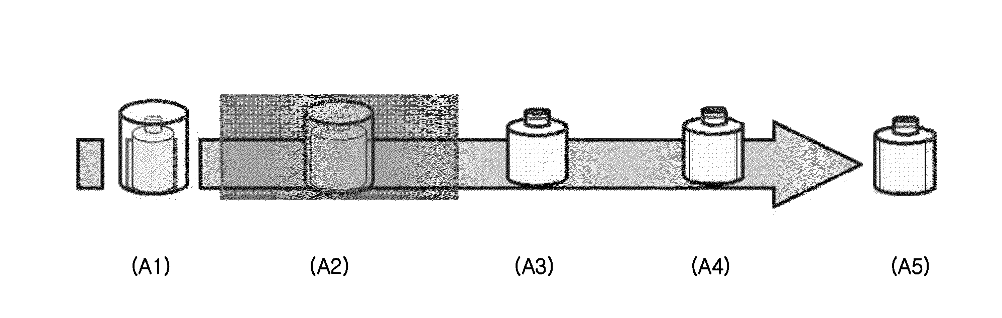
The present invention is a hot air tunnel system apparatus and a labeling method using it to prevent labeling defects such as loose labels or irregular shrinkage. The system has three zones, a preheating zone, a labeling zone, and a cooling zone, that work together to minimize these defects. The preheating zone helps to expand the product being labeled while the labeling zone allows the heat-shrinkable label to shrink uniformly around the product. The cooling zone prevents loose labels from sticking to the product. Overall, this hot air tunnel system apparatus helps to produce higher quality and more reliable labels on products.
Problems solved by technology
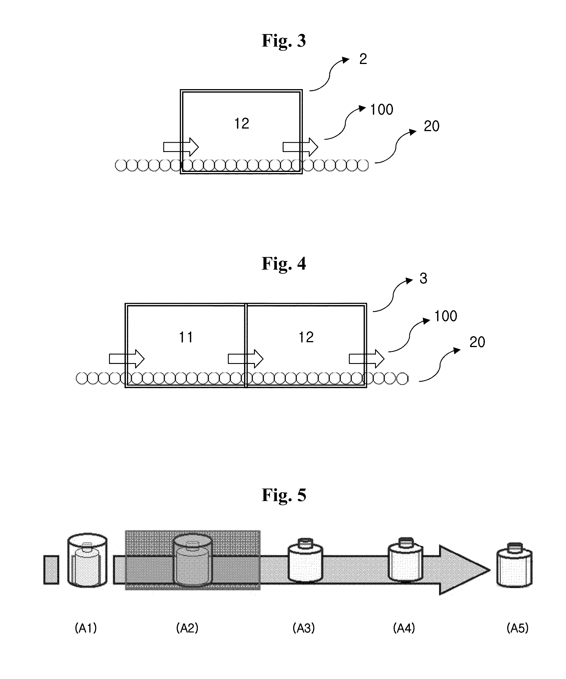
However, heat-shrink labeling of polyethylene-based products such as HDPE products in a conventional system apparatus may involve such problems as loose labels, film curl, or irregular shrinkage because preheating and cooling stages of the polyethylene-based products are not employed. FIG. 5 demonstrates how loose labels are produced in a conventional hot air tunnel having 1 or 2 zones only.
Also, a failure to provide uniform hot air in the tunnel could cause irregular shrinkage.
Method used
Image
Click on the blue label to locate the original text in one second.
Reading with bidirectional positioning of images and text.
Examples
example 1
Hot Air Tunnel System Apparatus Equipped with Preheating Zone, Labeling Zone, and Cooling Zone
[0044]In accordance with the present invention, a hot air tunnel system apparatus equipped with a preheating zone, a labeling zone, and a cooling zone was prepared.
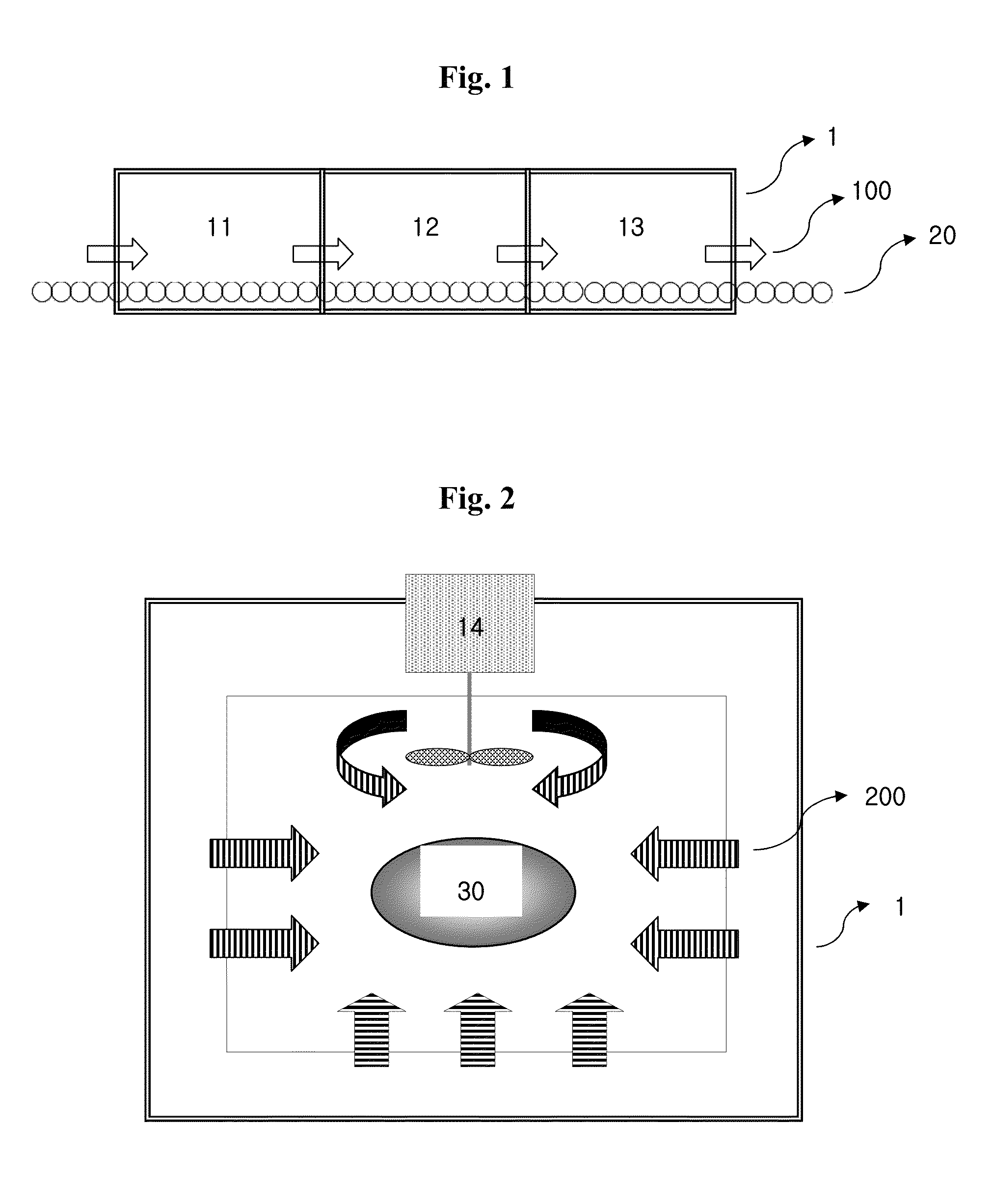
[0045]Specifically, the above apparatus was designed to convey a product to be labeled through the preheating zone, the labeling zone, and the cooling zone, in sequence, by way of a conveyer belt while the labeling process takes place.
[0046]The temperatures in the preheating zone, the labeling zone and the cooling zone were kept at 60° C., 120° C., and 70° C., respectively. On both sides and on the bottom of each zone, fan heaters were provided to blow hot air at flow rates of 20 m / s, 30 m / s, and 30 m / s, in the respective zones. An air circulation system was provided on the top of each zone for the circulation of hot air therein. The speed of the conveyer belt was controlled to allow the product to stay for 30 seconds in each zon...
examples 2 to 4
Hot Air Tunnel System Apparatuses Equipped with Preheating Zone, Labeling Zone and Cooling Zone
[0047]Hot air tunnel system apparatuses were prepared in the same manner as in Example 1 except that various temperatures, flow rates of hot air, and residence times of the products shown in Table 1 were employed.
Heat-Shrink Labeling Process
[0048]The hot air tunnel system apparatuses of Comparative Examples 1 and 2 and of Examples 1 to 4 were used to label HDPE containers with heat-shrinkable labels.
[0049]Specifically, HDPE containers covered with heat-shrinkable labels were conveyed through the preheating zone, the labeling zone and / or the cooling zone of each apparatus in order to label said HDPE containers with the heat-shrinkable labels.
[0050]For the heat-shrinkable label, SKYROL® heat-shrinkable films available from SKC Co. Ltd. were used, and a typical shampoobottle was used for the HDPE container.
Test: Evaluation of Labeling Quality
[0051]In order to evaluate the heat-shrink labelin...
PUM
Property
Measurement
Unit
Temperature
aaaaa
aaaaa
Temperature
aaaaa
aaaaa
Temperature
aaaaa
aaaaa
Abstract
A hot air tunnel system apparatus comprising a preheating zone, a labeling zone, and a cooling zone with a transporting member provided through the lower parts of said zones to convey a product to be labeled from the preheating zone to the cooling zone, wherein each zone is equipped with fan heaters on both sides and on the bottom thereof, and also equipped with an air circulation system on the top thereof, which can minimize such labeling defects as loose labels, film curl, and irregular shrinkage when polyethylene-based products are labeled with heat-shrinkable labels.
Description
FIELD OF THE INVENTION[0001]The present invention relates to a hot air tunnel system apparatus that enables labeling of polyethylene-based packaging with heat-shrinkable labels and a labeling method using same.BACKGROUND OF THE INVENTION[0002]Polyethylene (PE) is widely used in different applications due to its good moldability, particularly high-density polyethylene (HDPE) is widely used for packaging of household items such as shampoo and lotion owing to its excellent durability and mechanical properties. Polyethylene, especially HDPE, has a high thermal expansion coefficient and begins to expand around 50° C.[0003]Meanwhile, various label forms are in use for plastic products to provide information such as names and contents. Self-adhesive paper labels were largely used traditionally; heat-shrinkable labels have recently become more popular to accommodate the needs for different types of printings to attract customers' attention or to be used for a full wrapping, which provides m...
Claims
Application Information
Patent Timeline
Application Date:The date an application was filed.
Publication Date:The date a patent or application was officially published.
First Publication Date:The earliest publication date of a patent with the same application number.
Issue Date:Publication date of the patent grant document.
PCT Entry Date:The Entry date of PCT National Phase.
Estimated Expiry Date:The statutory expiry date of a patent right according to the Patent Law, and it is the longest term of protection that the patent right can achieve without the termination of the patent right due to other reasons(Term extension factor has been taken into account ).
Invalid Date:Actual expiry date is based on effective date or publication date of legal transaction data of invalid patent.

