Vane carrier assembly

a technology of vane carrier and assembly, which is applied in the direction of machines/engines, liquid fuel engines, lighting and heating apparatus, etc., can solve the problems of component or engine damage, engine operation efficiency reduction, etc., and achieve the effect of reducing thermal expansion

Inactive Publication Date: 2017-12-05
SIEMENS ENERGY INC
View PDF20 Cites 5 Cited by
  • Summary
  • Abstract
  • Description
  • Claims
  • Application Information

AI Technical Summary

Benefits of technology

[0014]The control ring may be formed from a low thermal coefficient of expansion material to generally minimize thermal expansion and contraction of the control ring in a radial direction.
[0015]In accordance with a second aspect of the present invention, a method is provided for controlling clearance between tips of rotating blades and an inner surface of a vane support assembly within an engine casing of a gas turbine engine. The method may comprise providing a plurality of vane support panels positioned adjacent to one another to define the vane support assembly. The panels may be made of a first material. The method may further comprise providing a control ring adapted to be supported by the engine casing and made of a second material, and securing the vane support assembly to the control ring. The second material is thermally more stable than the first material.

Problems solved by technology

During operation of the gas turbine engine, fluid leakage through this clearance contributes to system losses, decreasing the operational efficiency of the engine.
However, it is necessary to maintain a clearance between the rotating and stationary components to prevent rubbing between the rotating and stationary components, which can lead to component or engine damage.

Method used


Image

  • Vane carrier assembly
  • Vane carrier assembly
  • Vane carrier assembly

Examples


first embodiment

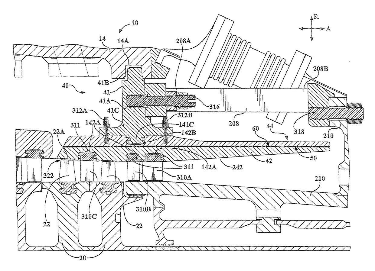
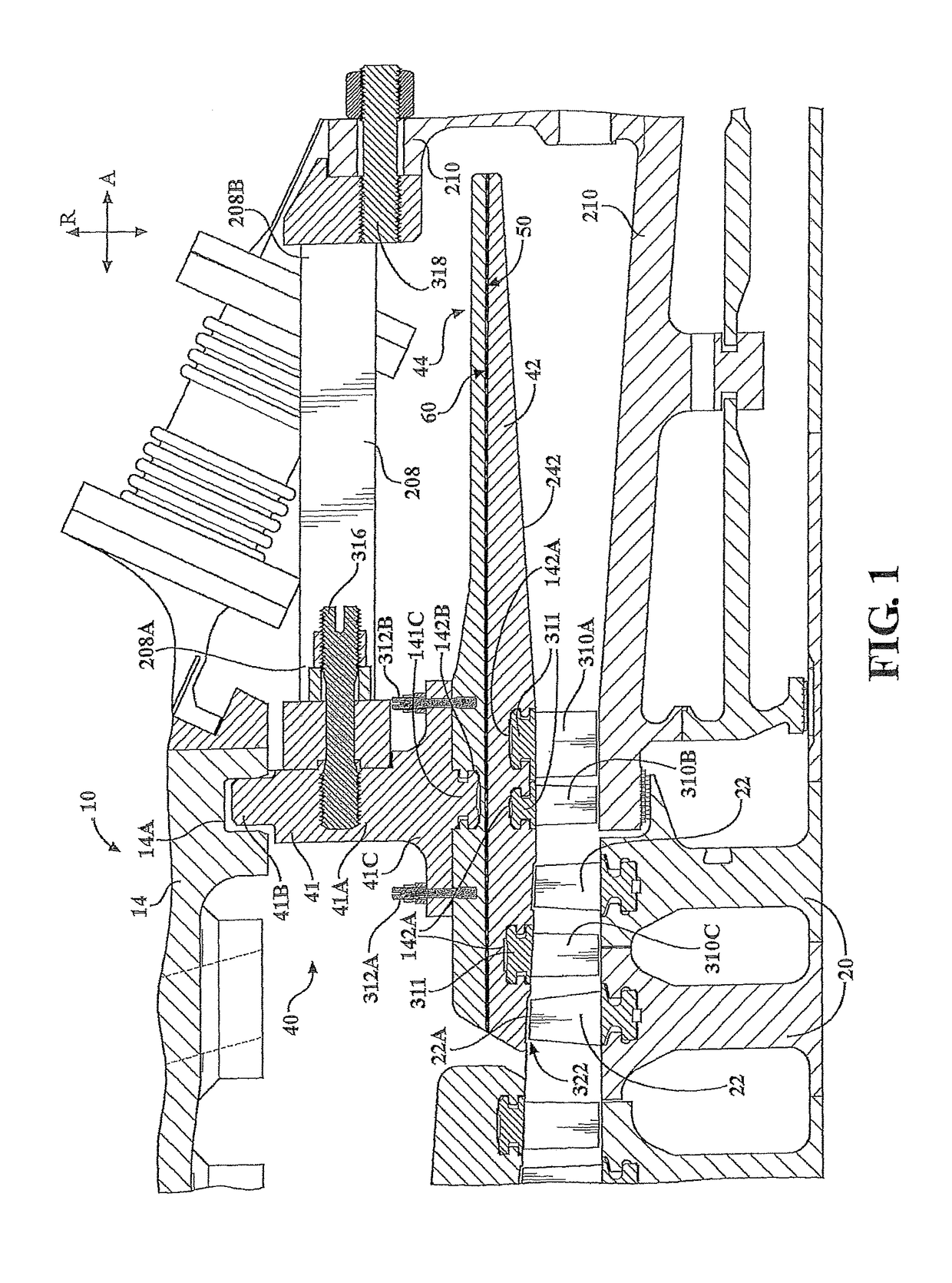
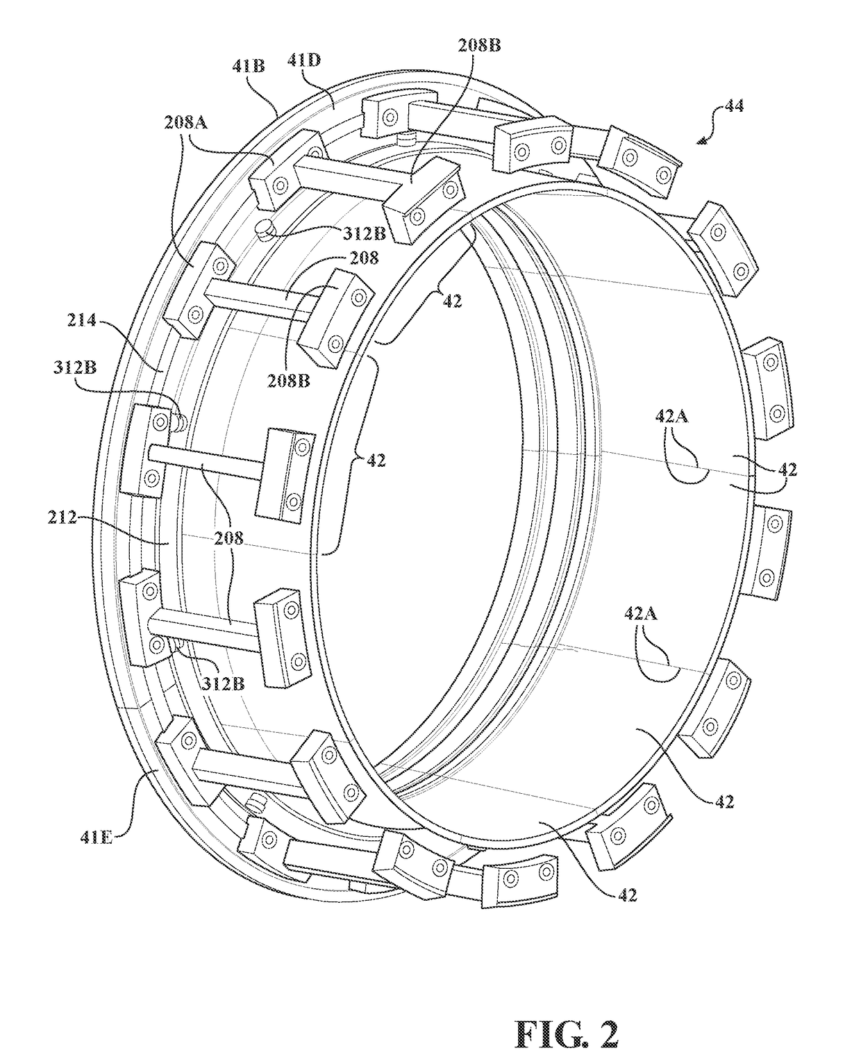
[0028]In accordance with the present invention, a vane carrier assembly 40 is provided for supporting vanes 310A-310C within the engine outer casing 14, see FIGS. 1-2. The vane carrier assembly 40 comprises an annular control ring 41 and a plurality of vane support panels 42 coupled to the control ring 41. The control ring 41 comprises a main body 41A, a radial outer flange 41B and a radial inner coupling member 41C. The flange 41B is loosely received in an annular recess 14A provided in the engine casing 14. In accordance with the present invention, the control ring 41 is formed from a material having a coefficient of thermal expansion lower than that of the outer casing 14 and the main engine rotor. For example, the outer casing 14 may be formed from a conventional steel alloy such as 2.25 Cr—Mo steel, the components of the main engine rotor may be formed from a conventional steel alloy, such as a NiCrMo alloy, while the control ring 41 may be formed from a material, such as one o...

second embodiment

[0039]A vane carrier assembly 400 constructed in accordance with the present invention is illustrated in FIG. 4, where elements in the assembly 400 similar to those used in the assembly 40 illustrated in FIG. 1 are referenced by the same numerals as used in FIG. 1. In this embodiment, the control ring 410 has an axial dimension which is greater than its radial dimension. The control ring 410 is smaller than the control ring 41 in the FIG. 1 embodiment; hence, less low coefficient of thermal expansion material is required to form the control ring 410 of the FIG. 4 embodiment as compared to the control ring 41 of the FIG. 1 embodiment. The control ring 410 includes a flange 410B that is loosely received in an annular recess 140A provided in the engine casing 140. Because the control ring flange 410B is loosely received in the annular recess 140A of the engine casing 140, the engine casing 140 is capable of moving radially relative to the flange 410B of the control ring 410 during engi...

third embodiment

[0040]A vane carrier assembly 500 constructed in accordance with the present invention is illustrated in FIG. 5, where elements in the assembly 500 similar to those used in the assembly 40 illustrated in FIG. 1 are referenced by the same numerals as used in FIG. 1. In this embodiment, each of the vane support panels 540 includes a first section 504 and a second section 506. First, second and third rows of first, second and third vanes 310A-310C, respectively, are coupled to the vane support panel first sections 504, see FIG. 5. The first sections 504 are formed integral with a control ring 541 from a material, which preferably comprises a low coefficient of thermal expansion, such as one of INCOLOY® Alloy 909 (a nickel-iron-cobalt alloy), INCOLOY® Alloy 939 (a nickel based alloy), or NILO® Alloy K (a nickel-iron-cobalt controlled-expansion alloy). The control ring 541 includes a flange 541A that is loosely received in an annular recess 14A provided in the engine casing 14. Because t...


PUM


Abstract

A vane carrier assembly is provided for supporting vanes within a main engine casing of a gas turbine engine. The vane carrier assembly comprises a plurality of vane support panels positioned adjacent to one another so as to define a vane support assembly. The support panels are assembled such that the support panels expand circumferentially to minimize radial expansion of the vane support assembly during operation of the gas turbine engine. A control ring is coupled to the main engine casing, and the vane support assembly is coupled to the control ring. The control ring may be formed from a material having a coefficient of thermal expansion less than that of the material from which the vane support assembly is formed.

Description

FIELD OF THE INVENTION[0001]The invention relates in general to gas turbine engines and, more specifically, to a vane carrier assembly for use in a gas turbine engine.BACKGROUND OF THE INVENTION[0002]A conventional combustible gas turbine engine includes a compressor, a combustor, and a gas turbine. The engine further comprises an outer casing which defines an outer section for each of the compressor, combustor and gas turbine. A rotor extends through the engine. The rotor portion extending through the compressor is defined by a plurality of discs. Each disc can host a row of rotating airfoils, commonly referred to as blades. The rows of blades alternate with rows of stationary airfoils or vanes. The vanes can be mounted to the casing via one or more vane carrier assemblies. A clearance is defined between tips of the blades and an inner surface of vane carrier support panels. During operation of the gas turbine engine, fluid leakage through this clearance contributes to system losse...

Claims


Application Information

Patent Timeline
Patent Type & Authority Patents(United States)
IPC IPC(8): F01D9/04F01D25/26F04D29/54F01D11/18F01D25/24
CPCF04D29/541F01D9/041F04D29/542F01D25/246F01D25/26F01D11/18
Inventor KIMMEL, KEITH D.WILSON, JACK
Owner SIEMENS ENERGY INC
Why Eureka
Try Eureka