Brushless motor

a brushless motor and motor body technology, applied in the direction of dynamo-electric machines, electrical equipment, supports/enclosements/casings, etc., can solve the problems of damage and short circuit, no configuration provided to prevent the crossing wire from falling out, and various flaws

Active Publication Date: 2013-06-27
AISAN IND CO LTD
View PDF2 Cites 25 Cited by
  • Summary
  • Abstract
  • Description
  • Claims
  • Application Information

AI Technical Summary

Benefits of technology

[0007]It is another object to provide a brushless motor, which prevents crossing wires from dropping out from a crossing wire holder part.

Problems solved by technology

No configuration is provided to prevent the crossing wires from dropping out.
As a result, dropout of the crossing wires causes various flaws such as damage and short-circuit.

Method used


Image

  • Brushless motor
  • Brushless motor
  • Brushless motor

Examples


first embodiment

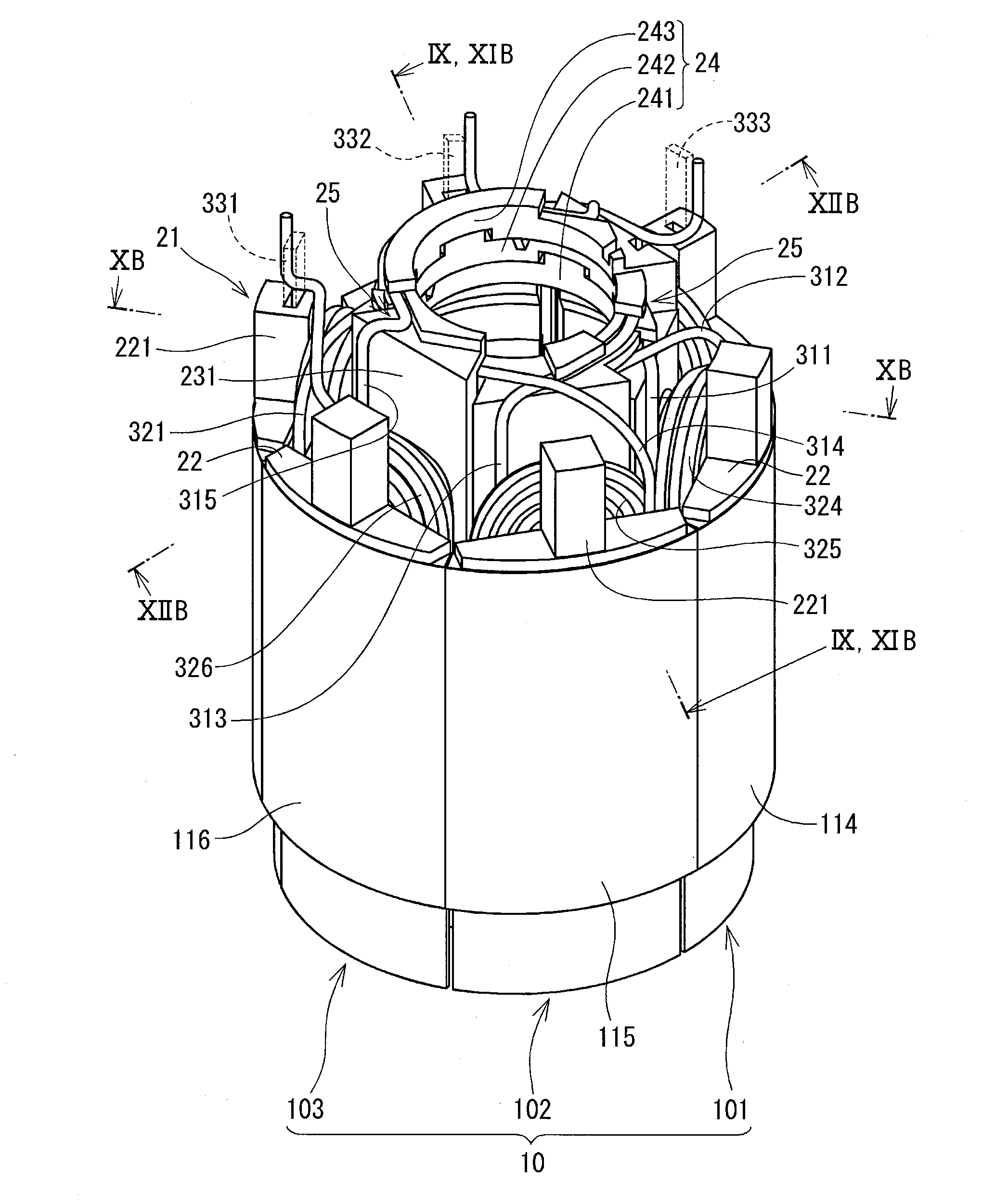
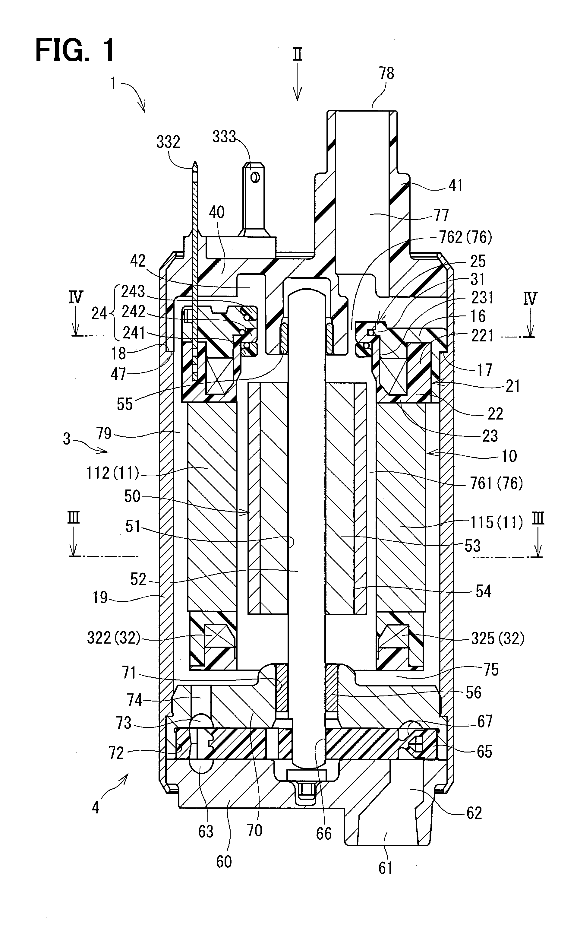
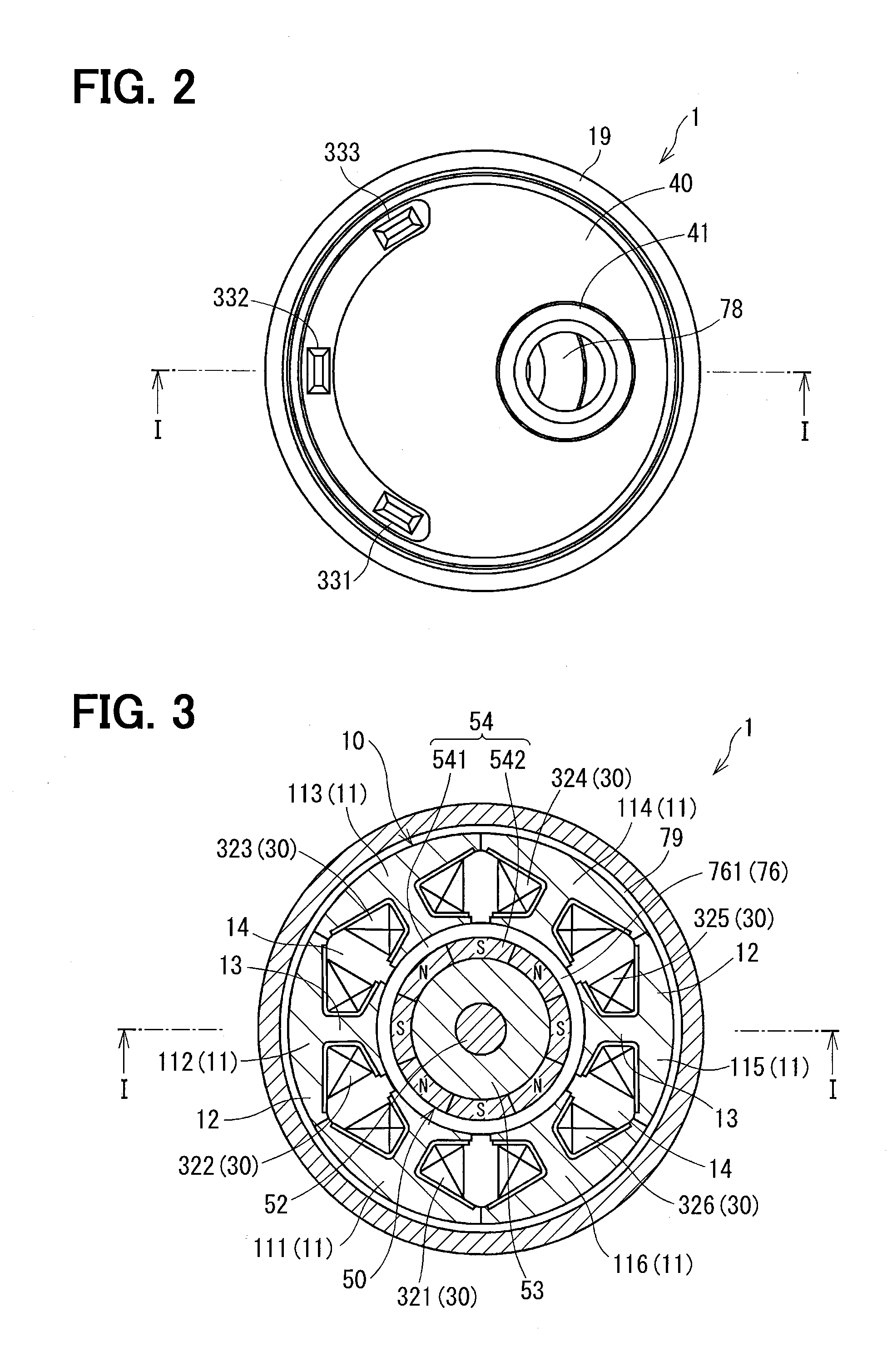
[0027]A brushless motor according to a first embodiment is provided in a fuel pump as shown in FIG. 1 to FIG. 14, particularly in FIG. 1 to FIG. 4.

[0028]A fuel pump 1 is configured to suction fuel stored in a fuel tank (not shown) from a suction port 61 shown in the lower part of FIG. 1 and discharges it to an internal combustion engine (not shown) from an output port 78 shown in the upper part of FIG. 1. The fuel pump 1 is divided into a motor part 3 and a pump part 4. An outer frame is formed of a housing 19, a pump cover 60, an end cover 40 and the like. In the following description about the fuel pump 1, the upper part and the lower part in FIG. 1 are referred to as a discharge port 78 side and a suction port 61 side.

[0029]The housing 19 is made of a metal such as iron and formed in a cylindrical shape. The pump cover 60 closes an end part of the suction port 61 side of the housing 19. The pump cover 60 is crimped into an inside part at a fringe of its end part, which is at the ...

second embodiment

[0061]A fuel pump according to a second embodiment is shown in FIG. 15. A fuel pump 2 according to the second embodiment is different from the fuel pump 1 of the first embodiment only in that a check valve part 80 is provided within the discharge passage 77 at a position immediately inside the discharge port 78. Substantially same parts are designated by the same reference numerals to simplify the description.

[0062]In the check valve part 80, a rod-shaped valve member 81 and a support member 83 are provided in the discharge passage 77. The support member 83 is fixed to the discharge port 78 side of the discharge passage 77 to support one end part of the valve member 81 slidably. The valve member 81 is thus supported reciprocally in the axial direction in the discharge passage 77. The other end part of the valve member 81 is formed semi-spherically to be able to butt a valve seat 82 formed in an intermediate part of the discharge passage 77.

[0063]When the pressure of fuel is boosted ...


PUM


Abstract

A motor part of a fuel pump is a brushless motor having a stator and a rotor. The stator has a core, a coil set and an insulator, which holds the core and the coil set in an insulated manner. The coil set has a plurality of coils wound about a tooth part and a plurality of crossing wires connecting the coils. The insulator is formed by stacking central ring parts of a plurality of stator units in an axial direction. At least one of crossing wire holder parts is formed of a combination of guide projections, which are formed on the different central ring parts. The length of the brushless motor in the axial direction can thus be shortened.

Description

CROSS REFERENCE TO RELATED APPLICATION[0001]This application relates to and incorporates herein by reference Japanese patent application No. 2011-279601 filed on Dec. 21, 2011.TECHNICAL FIELD[0002]The present disclosure relates to a brushless motor.BACKGROUND ART[0003]According to a conventional brushless motor, current supply to a coil set wound about a core of a stator is controlled to continuously switch over magnetic field so that a rotor provided inside the stator is rotated. A coil wire wound about one of a plurality of core parts, which forms the core, and a coil wire wound about another core part are connected by crossing wires. Holder parts for holding the crossing wires are formed on the stator.[0004]For example, in JP 2007-129847A (US 2007 / 0103014 A1), a positioning member including a plurality of projections arranged in a radial direction is formed. Each crossing wire is laid between the adjacently arranged projections of the positioning member so that the plurality of c...

Claims


Application Information

Patent Timeline
Patent Type & Authority Applications(United States)
IPC IPC(8): H02K3/38
CPCH02K3/38H02K2203/06H02K5/12H02K3/522
Inventor FURUHASHI, DAIJINAGATA, KIYOSHIOOTAKE, MASAYA
Owner AISAN IND CO LTD
Why Eureka
Try Eureka