Button switch three-way valve

a three-way valve and button switch technology, applied in multiple-way valves, mechanical devices, transportation and packaging, etc., can solve the problems of inconvenient switch and large switch force, and achieve the effect of easy assembly and clever driving

Active Publication Date: 2013-07-04
XIAMEN SOLEX HIGH TECH IND CO LTD
View PDF14 Cites 10 Cited by
  • Summary
  • Abstract
  • Description
  • Claims
  • Application Information

AI Technical Summary

Benefits of technology

[0029]1. The there way valve, the priority valve, the button and the lock catch structure (the cooperation of the lock grooves and the lock tooth) are cleverly combined; the sliding of the valve shaft is controlled by the swinging of the button, the on-off of the priority valve is controlled by the sliding of the valve shaft, the switch of at least two outlet waterways to connect to the inlet waterway is controlled by the on-off of the priority valve, so that the switch is energy saving, the switch is not influenced by the water pressure, the switch state is held and the switch is convenient;
[0030]2. Three outlet states are being held, which is realized by the cooperation of the three-way valve, the priority valve, the button and the lock catch structure, the structure is simple and the switch is convenient;
[0031]3. The fixation unit includes a body and a priority valve cover, the priority valve cover is assembled inside the assembly groove of the body to form the inlet waterway and the outlet waterways, the priority valve is assembled between each outlet waterway and the inlet waterway, the structure is clever and simple with small size.
[0032]4. The priority valve cover is pivot joint with a pivot seat and a control seat, the pivot seat is disposed with a pivot groove, the control seat is disposed with control surface, the structure is simple, it works easy with low cost;
[0034]6. The valve shaft is connected to the connection groove of the button, the connection edge of the connection groove is coupled to the sliding groove of the valve shaft, so that the valve shaft moves up and down when the connection groove of the button swings, the assembly is easy and the driving is clever.

Problems solved by technology

This kind of switch of waterways by rotating the valve spool has disadvantages as below: it needs large switch force, and the switch is inconvenient.

Method used


Image

  • Button switch three-way valve
  • Button switch three-way valve
  • Button switch three-way valve

Examples


first embodiment

The First Embodiment

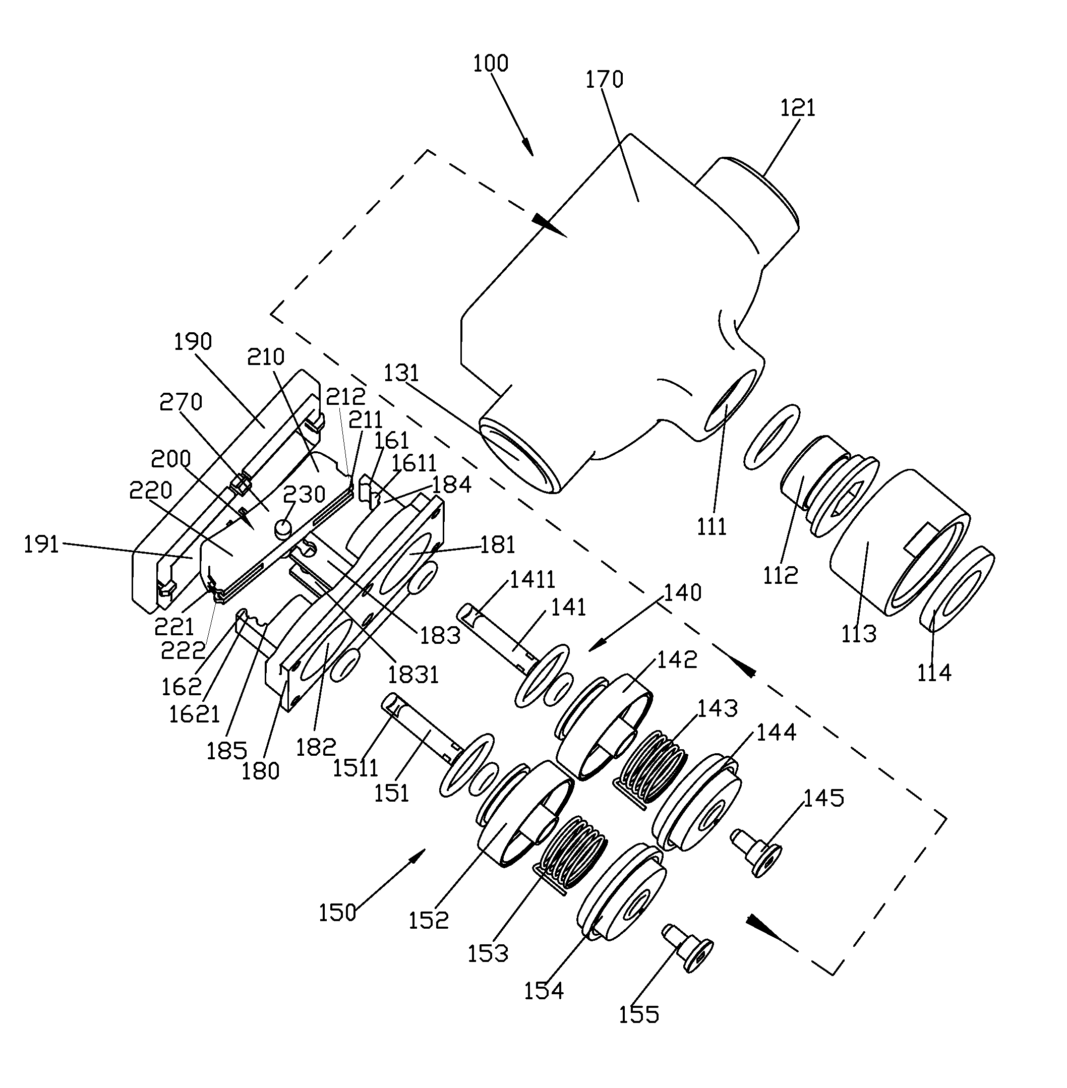
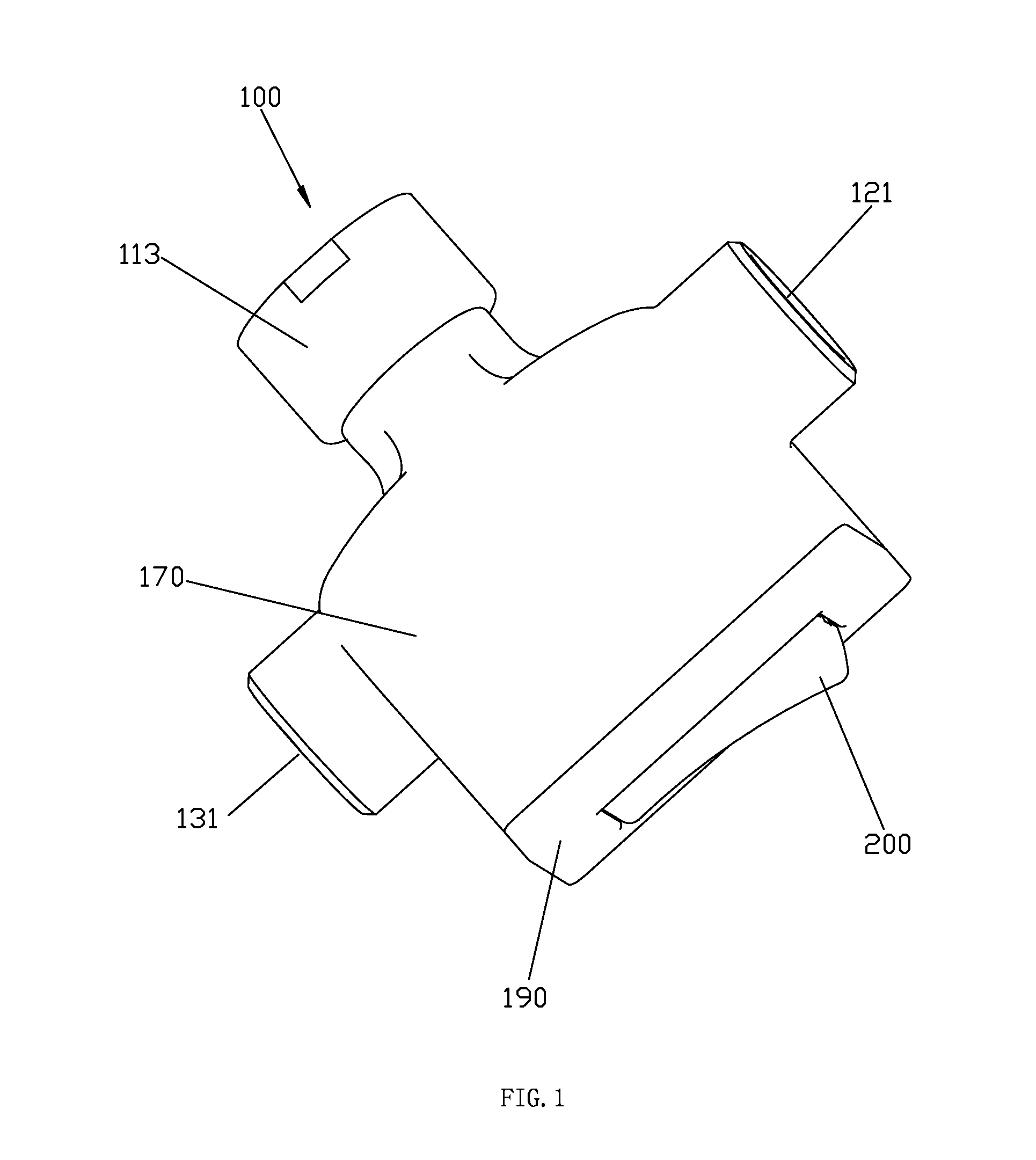
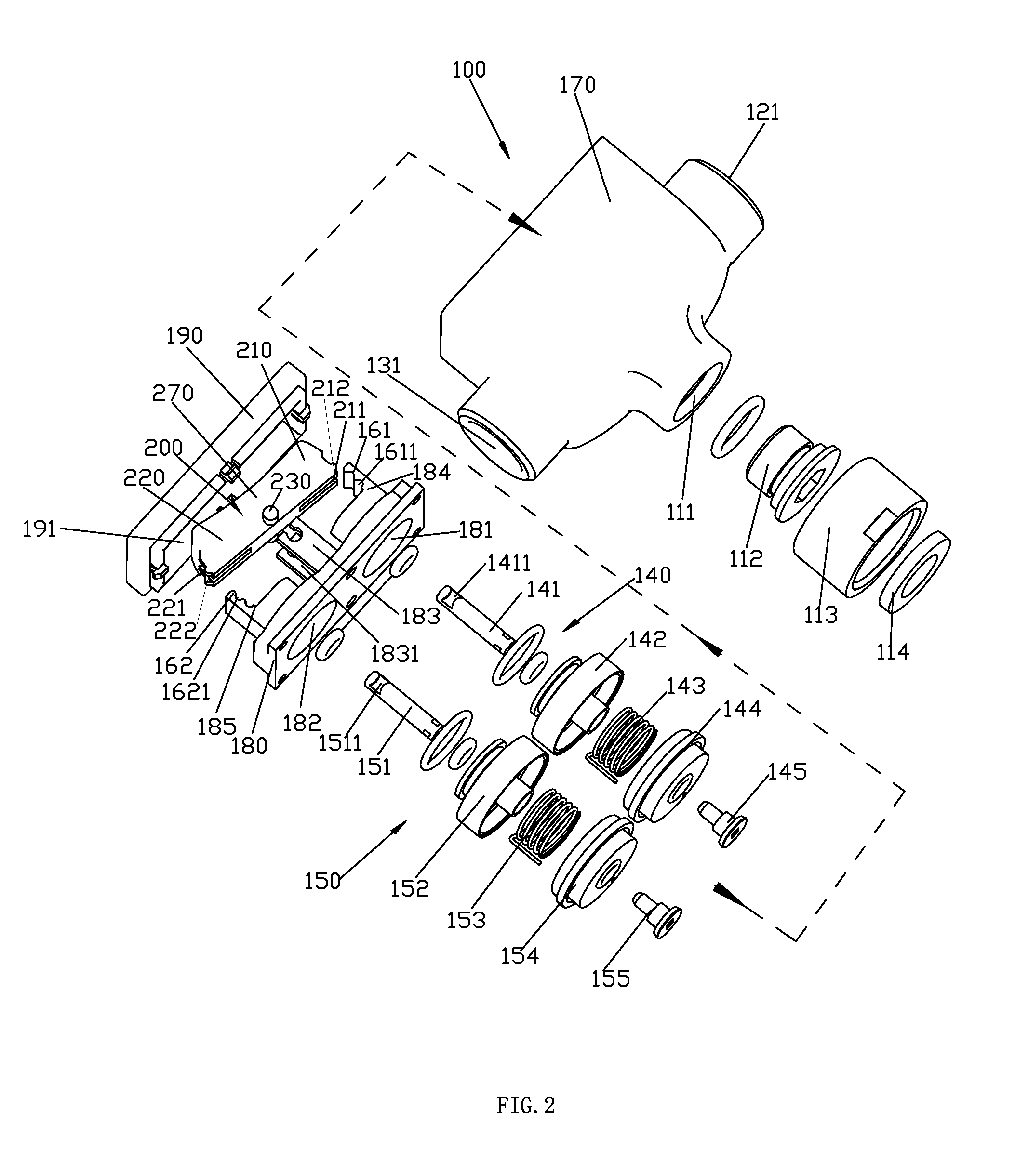
[0050]Refer to the FIG. 1 to the FIG. 6. A button switch three-way valve includes a fixation unit 100 and a button 200. The fixation unit 100 is disposed with an inlet waterway 110, an outlet waterway I 120 and an outlet waterway II 130. A priority valve I 140 is connected between the outlet waterway I 120 and the inlet waterway 110, and a priority valve II 150 is connected between the outlet waterway II 130 and the inlet waterway 110. The priority valve I 140 has a valve shaft I 141, a priority valve body I 142, a spring I 143, a rubber block I 144 and a priority valve spool I 145, and the priority valve II 150 is disposed with a valve shaft II 151, a priority valve body II 152, a spring II 153, a rubber block II 154 and a priority valve spool II 155. The priority valve I and the priority valve II are existing technology and not further described here. The valve shaft I 141 and the valve shaft II 151 are separately sliding up and down in an upper, central and lo...

second embodiment

The Second Embodiment

[0061]Please refer to the FIG. 8 and FIG. 9, which are provided with another embodiment of the button switch three-way valve.

[0062]The priority valve I 140 is disposed with a valve shaft I 1411, a priority valve body I 142, a spring I 143, a rubber block I 144, a priority valve spool I 145 and a gland I 146; and the priority valve II 150 is disposed with a valve shaft II 1511, a priority valve body II 152, a spring II 153, a rubber block II 154, a priority valve spool II 155 and a gland II 156. The priority valve I 140 and the priority valve II 150 are existing technology and not further described here. The valve shaft 141 and the valve shaft II 151 are separately sliding up and down in an upper, central and lower control position in the fixation unit 100. The decompression of the decompression waterway I of the priority valve I 140 is controlled by the sliding up and down of the valve shaft I 141, and the decompression of the decompression waterway II of the pr...

third embodiment

The Third Embodiment

[0067]Refer to the FIG. 10 to FIG. 13, which is provided with another embodiment of the button switch three-way valve.

[0068]A button switch three-way valve includes a fixation unit 100. The fixation unit 100 is disposed with an inlet waterway 110, an outlet waterway I 120 and an outlet waterway II 130. The priority valve I 140 has a valve shaft I 141 and the priority valve II 150 has a valve shaft II 151. the on-off of the outlet waterway 120 to the inlet waterway 110 is controlled by the sliding of the valve shaft I 141, the on-off of the outlet waterway II 130 to the inlet waterway 110 is controlled by the sliding of the valve shaft II 151;

[0069]The fixation unit 100 includes a body 170, a priority valve cover 180 and a cover 190. The body 170 includes an inlet 111, an outlet I 121, an outlet II 131 and an assembly groove 171. The assembly groove 171 is connected the inlet 111 to the outlet I 121 and the outlet II 131. In this embodiment, the body 170 is furthe...


PUM


Abstract

A button switch three-way valve includes a fixation unit disposed with an inlet waterway and two outlet waterways. A priority valve is disposed between each outlet waterway and the inlet waterway. The on-off of the outlet waterway to the inlet waterway is controlled by the sliding of the valve shaft in each priority valve. The fixation unit is disposed with two control surfaces opposite to each other, each disposed with lock grooves. A button is disposed between the two control surfaces, with a central part and two connection parts in the two sides of the central part. The central part is pivot joint to the fixation unit. Two connection parts are separately connected to the two valve shafts to control the sliding of the two valve shafts, the exterior sides of the two connection parts are disposed with lock tooth to couple to the lock grooves.

Description

FIELD OF THE INVENTION[0001]The present invention relates to a button switch three-way valve.BACKGROUND OF THE INVENTION[0002]The existing three-way valve includes a body and a valve spool. The body is disposed with an inlet waterway and two outlet waterways. The two outlet waterways are connected to the inlet waterway. The valve spool is rotated and connected to the body inside. The two outlet waterways are switched to connect to the inlet waterway by the relatively rotation of the valve spool and the body. This kind of switch of waterways by rotating the valve spool has disadvantages as below: it needs large switch force, and the switch is inconvenient.SUMMARY OF THE INVENTION[0003]The present invention is provided with a button switch three-way valve, which overcomes the problems of the existing three-way valve that it needs large switch force and the switch is inconvenient.[0004]The technical proposal of the present invention to solve the technical problem is as below:[0005]A bu...

Claims


Application Information

Patent Timeline
Patent Type & Authority Applications(United States)
IPC IPC(8): F16K11/20
CPCF16K11/20F16K11/168Y10T137/86879H01H23/30E03C2201/30B05B1/1609
Inventor ZHOU, HUASONGGUO, FULICHEN, JIANMINCHEN, BIN
Owner XIAMEN SOLEX HIGH TECH IND CO LTD
Why Eureka
Try Eureka