Rotation rate sensor and method for operating a rotation rate sensor

a technology of rotation rate sensor and sensor, which is applied in the direction of acceleration measurement using interia force, turn-sensitive devices, instruments, etc., can solve the problems of high cost, spring elements used for suspending, and the suppression of quadrature signals, so as to achieve the effect of considerably reducing quadrature signals

Active Publication Date: 2013-07-11
ROBERT BOSCH GMBH
View PDF11 Cites 22 Cited by
  • Summary
  • Abstract
  • Description
  • Claims
  • Application Information

AI Technical Summary

Benefits of technology

[0006]In contrast to the related art, the rotation rate sensor according to the present invention and the method for operating a rotation-rate sensor according to the present invention have the advantage that the quadrature signal is considerably reduced. This is achieved by having the detection springs connect to the force transmission elements in the area of vibrational nodes.

Problems solved by technology

The quadrature signal has to be suppressed, in a costly manner, by suitable measures during the design of the rotation rate sensor, for instance, by actively connected compensation electrodes, and during the electrical processing of the measuring signal.
The main cause of the quadrature signal in micromechanical rotation rate sensors is that the spring elements used for suspending the Coriolis elements and drive means are not able to be processed ideally because of production tolerances.

Method used


Image

  • Rotation rate sensor and method for operating a rotation rate sensor
  • Rotation rate sensor and method for operating a rotation rate sensor
  • Rotation rate sensor and method for operating a rotation rate sensor

Examples


Embodiment Construction

[0022]In the various figures, identical parts have been provided with the same reference symbols and are therefore usually labeled or mentioned only once.

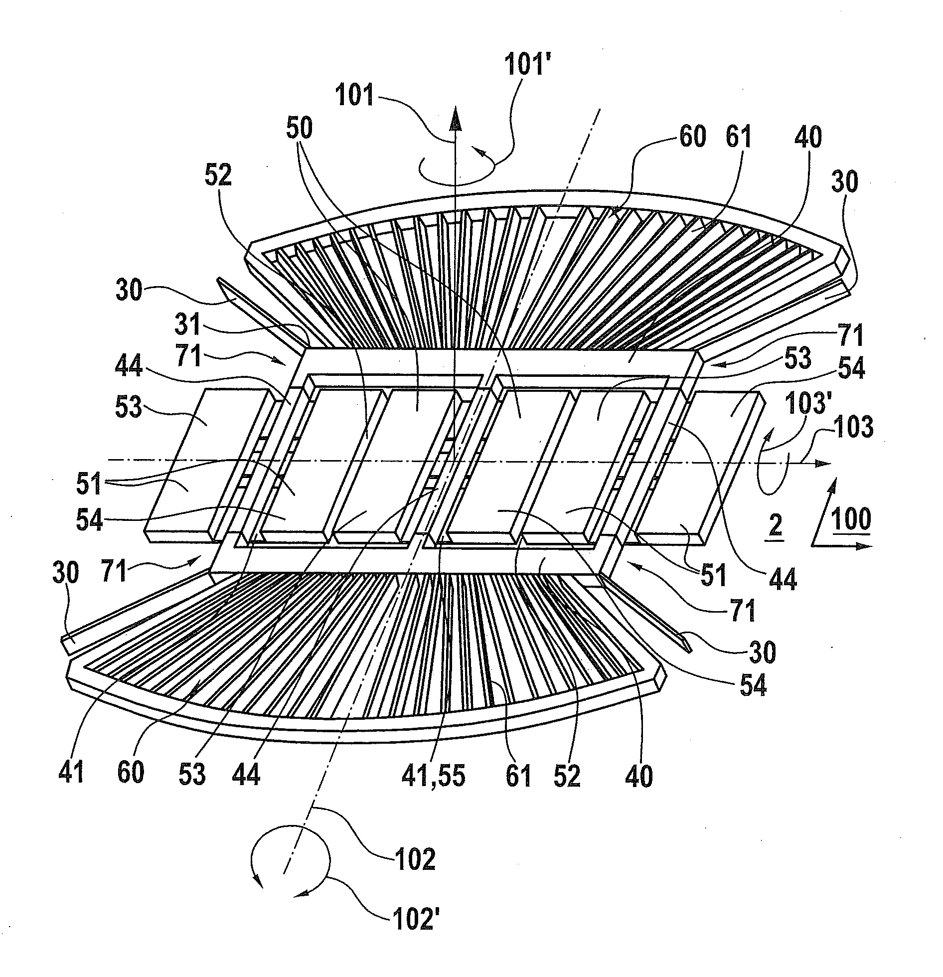
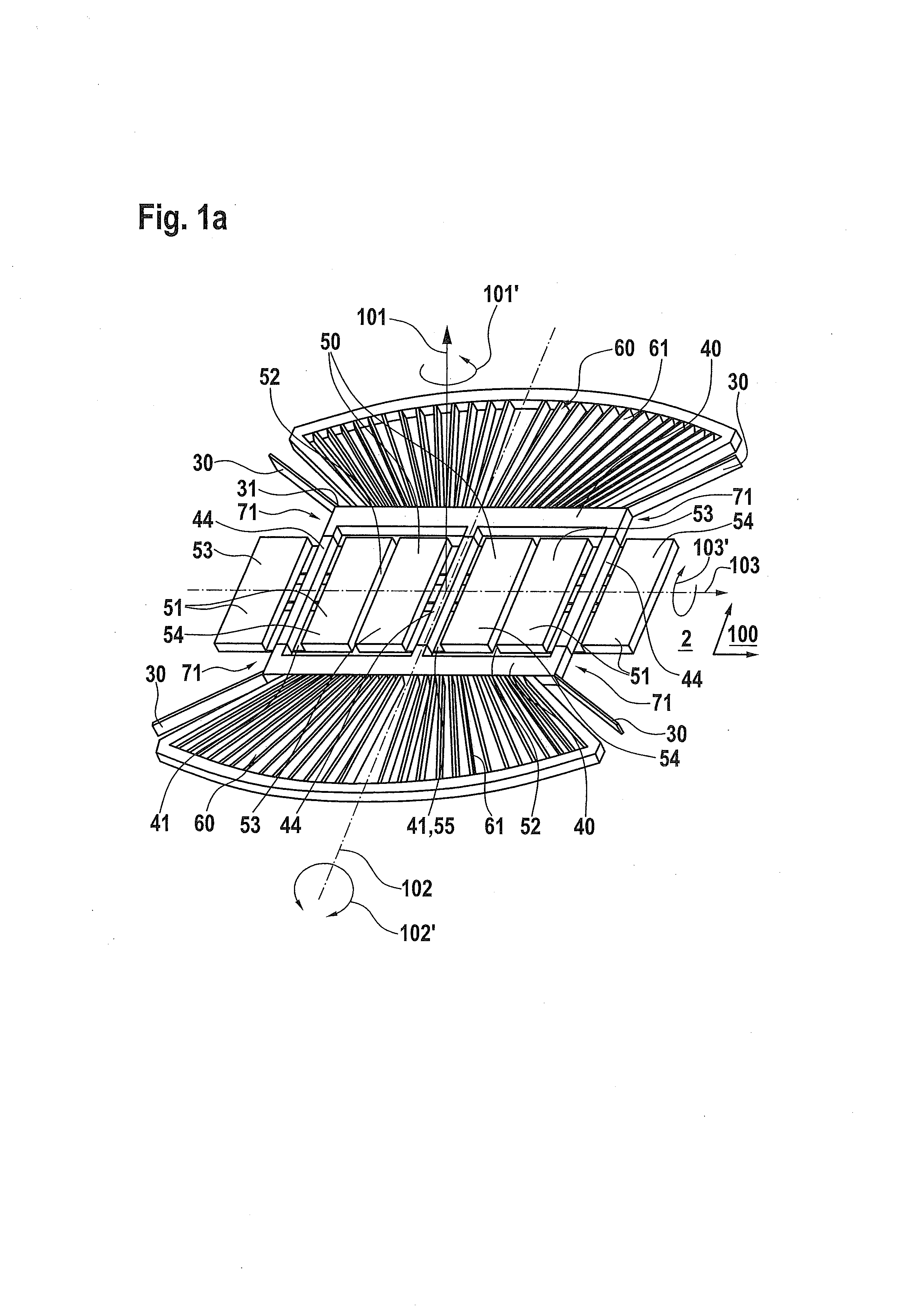
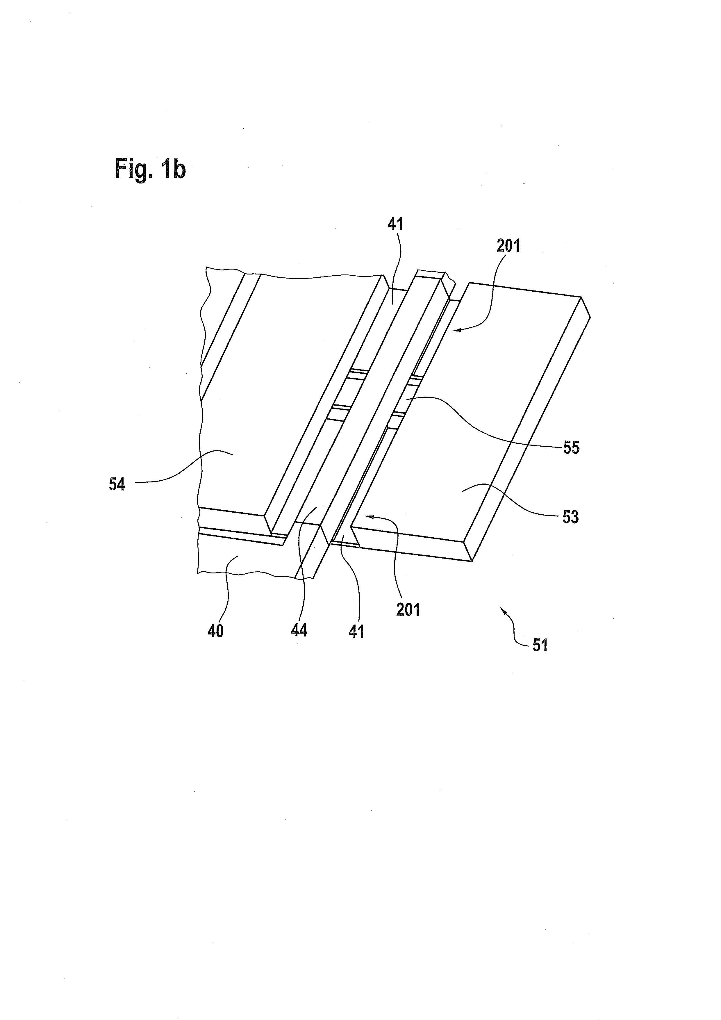
[0023]FIGS. 1a, 1b and 1c show schematic views of a rotation rate sensor 1 according to a first exemplary embodiment of the present invention. Rotation rate sensor 1 has a substrate 2 having a main extension plane 100. Substrate 2 preferably includes a silicon substrate, which has been patterned in a semiconductor production process. Rotation rate sensor 1 also has a seismic mass 50 and two additional seismic masses 51, seismic mass 50 being situated between the two additional seismic masses 51. Adjacent seismic mass 50 and additional seismic masses 51 are optionally connected to each other spring-elastically via a common spring region 52. Seismic mass 50 is pivotable about a drive axis that is parallel to main extension plane 100, and is able to be driven about drive axis 102, using a drive unit not illustrated, to perform a drive...


PUM


Abstract

A rotation rate sensor having a substrate including a main extension plane, force transmission elements that are movably fastened on the substrate using detection springs and a seismic mass are provided, the seismic mass being suspended over the force transmission elements, movably relative to the substrate, in such a way that the seismic mass is able to be excited, using a drive unit, to a drive vibration about a drive axis that is parallel to the main extension plane, and in response to the presence of a rotation rate that extends in parallel to the main extension plane and perpendicular to the drive axis, the seismic mass is excitable, as a result of Coriolis forces, to a detection vibration about a detection axis that is perpendicular to the main extension plane, the detection springs being connected to the force transmission elements in the region of the vibrational nodes.

Description

CROSS REFERENCE TO RELATED APPLICATION[0001]The present application claims priority to Application No. DE 10 2012 200 132.8, filed in the Federal Republic of Germany on Jan. 5, 2012, which is incorporated herein in its entirety by reference thereto.FIELD OF INVENTION[0002]The present invention relates to a rotation rate sensor and a method for operating a rotation-rate sensor.BACKGROUND INFORMATION[0003]German Application No. DE 101 08 196 A1, for example, describes a rotation rate sensor having Coriolis elements for measuring a rotation rate, which is located perpendicular on the substrate plane of the sensor. The sensor includes a first and a second Coriolis element, which are connected to each other via a spring, and are excited to vibrations parallel to a drive axis, a first and a second detection means detecting a deflection of the first and second Coriolis element parallel to a substrate plane, based on a Coriolis force acting upon the Coriolis elements, so that the difference...

Claims


Application Information

Patent Timeline
Patent Type & Authority Applications(United States)
IPC IPC(8): G01C19/56
CPCG01C19/5712G01C19/56G01C19/5719
Inventor KUHLMANN, BURKHARDLIEWALD, JAN-TIMO
Owner ROBERT BOSCH GMBH
Why Eureka
Try Eureka