
Method And System For Determining Camera Parameters From A Long Range Gradient Based On Alignment Differences In Non-Point Image Landmarks

a long range gradient and landmark technology, applied in image analysis, instruments, computing, etc., can solve problems such as difficulty in detecting a sufficient number of landmark point features continuously from all camera field-of-views, target not practical for outdoor-based cameras, and inability to meet the needs of outdoor sports environments, so as to improve camera calibration and reduce errors

Active Publication Date: 2013-07-11
DISNEY ENTERPRISES INC
View PDF6 Cites 38 Cited by
  • Summary
  • Abstract
  • Description
  • Claims
  • Application Information

AI Technical Summary

Benefits of technology

The present invention is a system and method for improving camera calibration. It involves receiving a camera image, a planar template pattern, a 3D geometry of a surface on which the planar template pattern is embedded, and a set of parameter values. The method then generates a warped template image by rendering the planar template pattern into a camera perspective based on the parameter values. An error image is generated by comparing the camera image with the warped template image, and the parameter values are adjusted to reduce the error between the camera image and the warped template image. The technical effect of this invention is to improve the accuracy and reliability of camera calibration.

Problems solved by technology

Camera calibration has been done on the basis of point-based targets like checkerboards, but such targets are not practical for outdoor-based cameras, such as those used in outdoor sporting environments.
Checkerboards are perhaps the most popular target because of their ease of use and manufacture, but in large outdoor scenes, checkerboards are impractical, as the necessary size may be on the order of meters.
Furthermore, detecting a sufficient number of landmark point features continuously from all camera field-of-views may be challenging given the highly dynamic steering of a broadcast camera (especially when covering a sporting event where camera panning and zooming may be rapid and extreme).
Calibration of a broadcast camera covering a dynamic event such as a football game, may be complicated by the fact that field surface is not planar.

Method used


Image

  • Method And System For Determining Camera Parameters From A Long Range Gradient Based On Alignment Differences In Non-Point Image Landmarks
  • Method And System For Determining Camera Parameters From A Long Range Gradient Based On Alignment Differences In Non-Point Image Landmarks
  • Method And System For Determining Camera Parameters From A Long Range Gradient Based On Alignment Differences In Non-Point Image Landmarks

Examples


Embodiment Construction

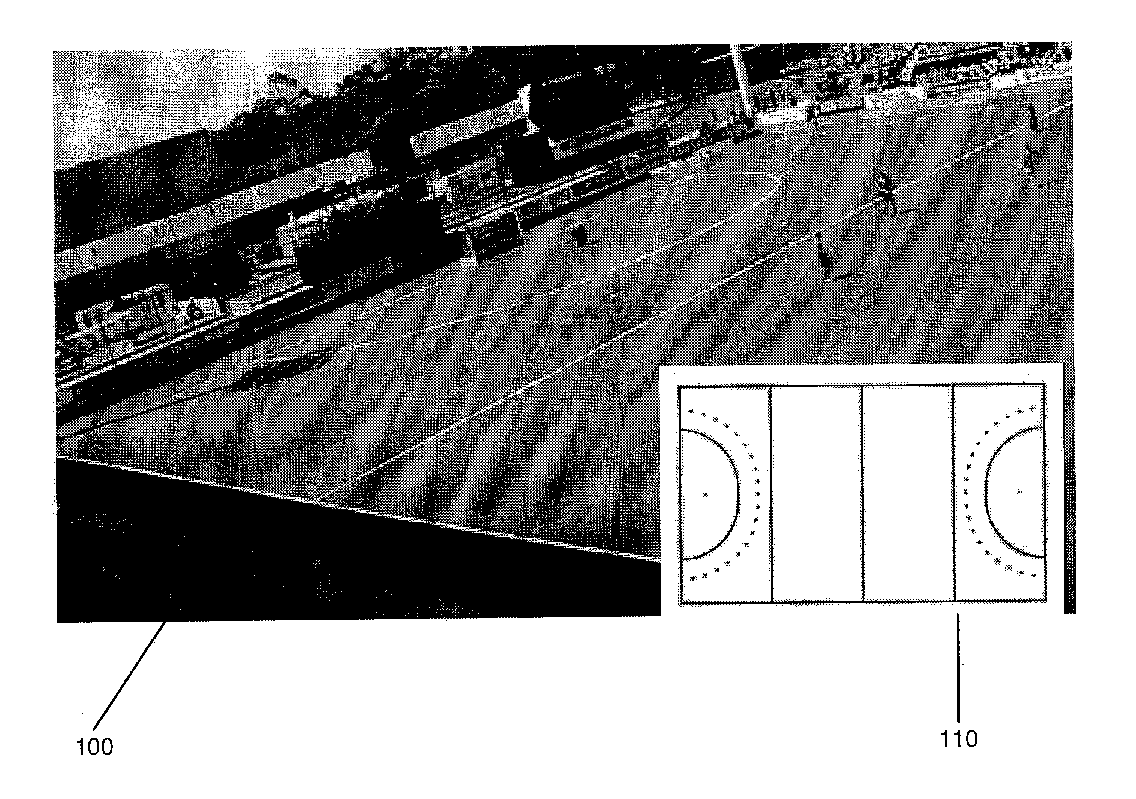
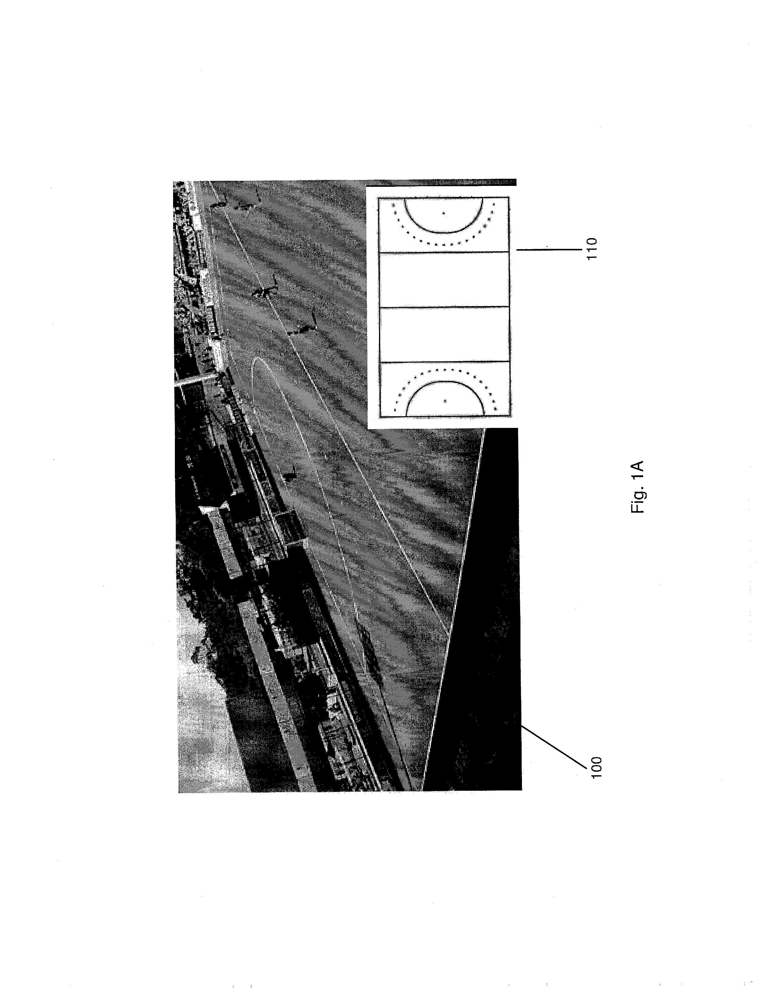
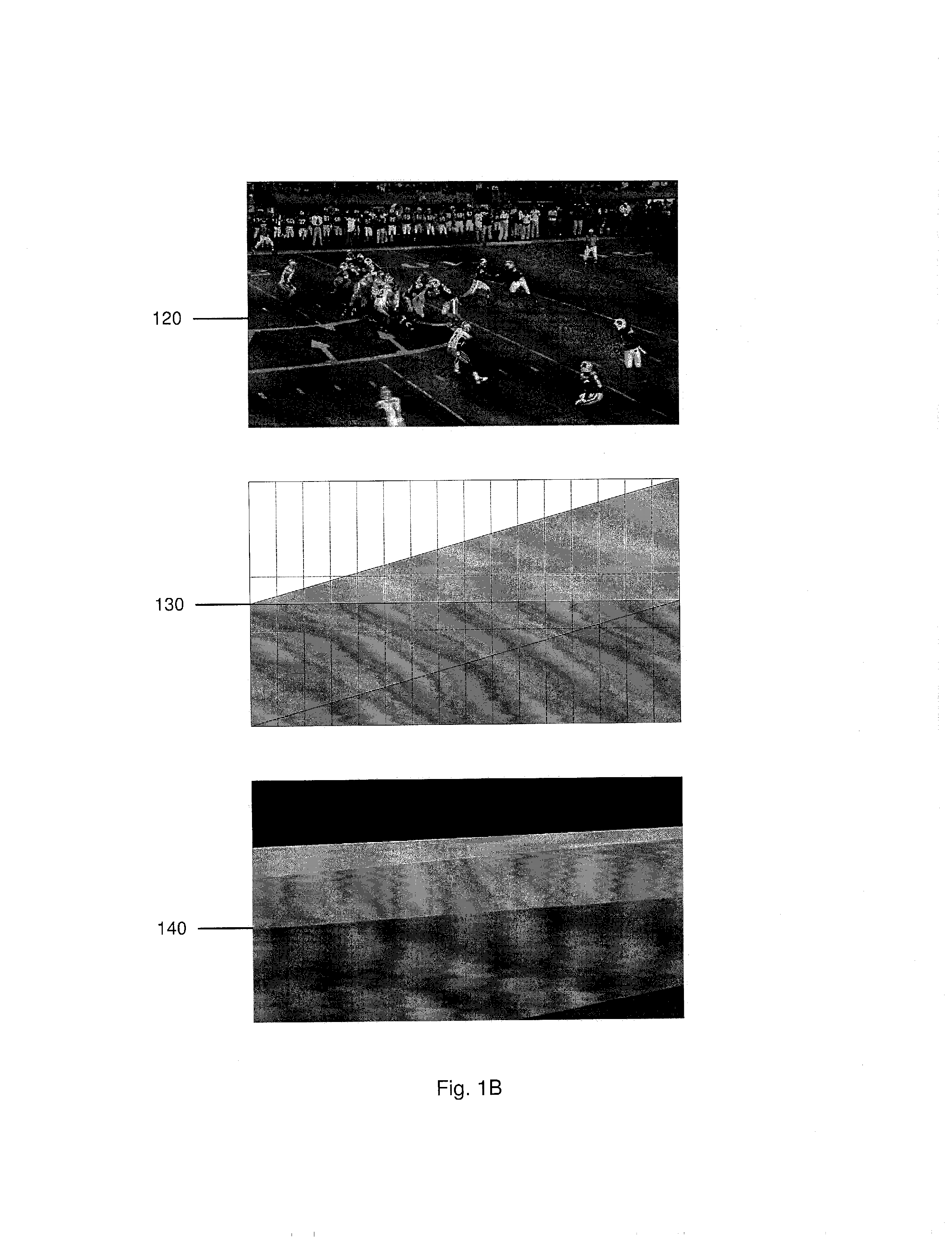
[0011]The exemplary embodiments may be further understood with reference to the following description and the appended drawings, wherein like elements are referred to with the same reference numerals. The exemplary embodiments describe methods and systems for calibrating a camera by aligning non-point landmarks in a known reference image to non-point landmarks in an image taken by the camera. More specifically, the calibration in the present application estimates intrinsic, extrinsic, and lens distortion camera parameters by aligning a surface at the scene (e.g. an overhead template / image of the ground) to the surface's image projection as captured by the camera using gradient-based image alignment optimization in which an image warping function is defined. Upon determining an initial set of camera parameters, these may be used for subsequent computations for a non-planar world image calibration by 1) partitioning the reference image into multiple planar patterns (manifolds) and 2) ...


PUM


Abstract

A system and method improves a camera calibration. The method includes receiving a camera image, a planar template pattern, a 3D geometry of a surface on which the planar template pattern is embedded, and a set of parameter values. The method includes rendering the planar template pattern into a camera perspective based on the parameter values to generate a warped template image. The method includes generating an error image including at least one non-zero difference between the camera image and the warped template image. The method includes adjusting the parameter values to reduce an error between the camera image and the warped template image.

Description

RELATED APPLICATION[0001]The present application claims priority to U.S. Ser. No. 61 / 584,544, filed on Jan. 9, 2012, which is incorporated by reference herein.BACKGROUND INFORMATION[0002]Camera calibration has been done on the basis of point-based targets like checkerboards, but such targets are not practical for outdoor-based cameras, such as those used in outdoor sporting environments. Standard camera calibration algorithms employ a two-stage approach that first identifies point correspondences between geometric features in an image and in the world (e.g., a checkerboard's junction points from its camera's image projection and from the real world positions), and then finds the perspective transformation parameters which minimize the distance between the transformed world points and their corresponding image locations. Checkerboards are perhaps the most popular target because of their ease of use and manufacture, but in large outdoor scenes, checkerboards are impractical, as the ne...

Claims


Application Information

Patent Timeline
IPC IPC(8): H04N13/02
CPCH04N13/0207G06T7/85H04N13/207
Inventor CARR, G. PETER K.MATTHEWS, IAIN
Owner DISNEY ENTERPRISES INC
Learn More