Optical unit with shake correcting function

Active Publication Date: 2013-07-18
NIDEC SANKYO CORP
View PDF4 Cites 51 Cited by
  • Summary
  • Abstract
  • Description
  • Claims
  • Application Information

AI Technical Summary

Benefits of technology

[0020]In the present invention, the flexible circuit board which is connected with the fixed body and the movable module is provided with a folded-back portion whose extended direction is reversed at a midway portion from a connected portion with the fixed body to a connected portion with the movable module, and portions of the folded-back portion which are superposed on each other are fixed to each other. Therefore, even when a

Problems solved by technology

Therefore, the flexible circuit board is deformed when the movable module is swung and thus, rigidity

Method used


Image

  • Optical unit with shake correcting function
  • Optical unit with shake correcting function
  • Optical unit with shake correcting function

Examples


first embodiment

(Entire Structure of Optical Unit for Photographing)

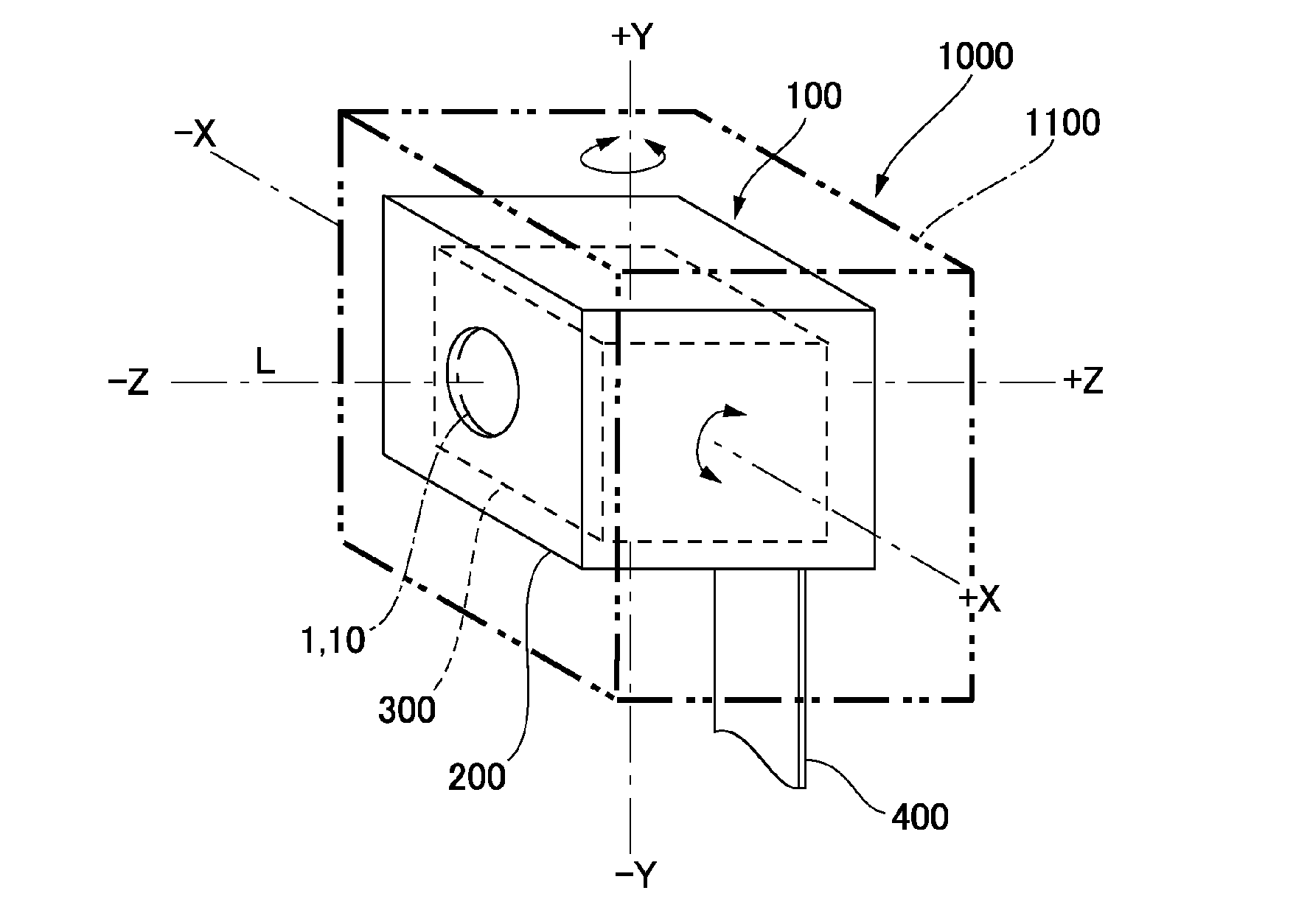
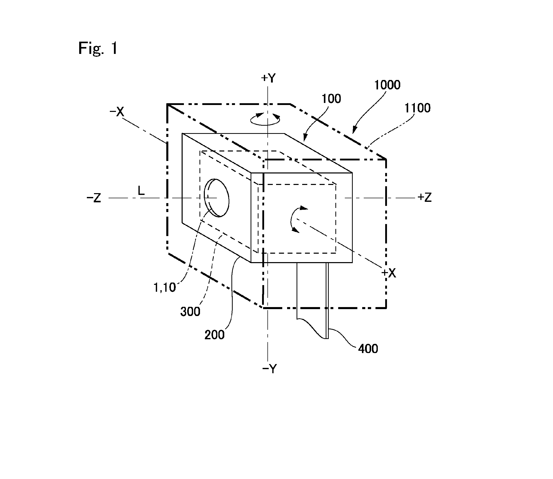
[0073]FIG. 1 is an explanatory view schematically showing a state in which an optical unit with a shake correcting function to which the present invention is applied is mounted on an optical device such as a cell phone or the like. An optical unit 100 (optical unit with a shake correcting function) shown in FIG. 1 is a thin camera used in an optical device 1000 such as a cell phone with a camera and is mounted in a supported state by a chassis 1110 of the optical device 1000 (device main body). In the optical unit 100, when a shake such as a hand shake is occurred in the optical device 1000 at the time of photographing, disturbance occurs in a photographed image.

[0074]In order to prevent this problem, the optical unit 100 in this embodiment is, as described below with reference to FIGS. 3(a), 3(b) and 3(c), provided with a movable module drive mechanism (not shown in FIG. 1) which swingably supports a movable module 300 including a...

second embodiment

[0103]FIGS. 7(a), 7(b) and 7(c) are explanatory views showing a state in which a flexible circuit board 400 is mounted in an optical unit 100 with a shake correcting function in accordance with a second embodiment of the present invention. FIG. 7(a) is a cross-sectional view showing the optical unit 100, FIG. 7(b) is a cross-sectional view showing a folded-back portion 425 of the flexible circuit board 400, and FIG. 5(c) is a cross-sectional view showing another folded-back portion 415 of the flexible circuit board 400. Basic structure in this embodiment is similar to the first embodiment and thus the same reference signs are used in common portions and their descriptions are omitted.

[0104]Also in this embodiment, similarly to the first embodiment, as shown in FIG. 7(a), in the folded-back portions 415 and 425 of the flexible circuit board 400, the portions where the flexible circuit board 400 is superposed on each other are fixed to each other. Specifically, as shown in FIG. 7(b), ...

third embodiment

[0108]FIGS. 8(a), 8(b), 8(c) and 8(d) are explanatory views showing a state in which a flexible circuit board 400 is mounted in the optical unit 100 with a shake correcting function in accordance with a third embodiment of the present invention. FIG. 8(a) is a cross-sectional view showing the optical unit 100, FIG. 8(b) is a perspective view showing a clip (restricting member) which is used for fixing the folded-back portions 415 and 425 of the flexible circuit board 400, FIG. 8(c) is a cross-sectional view showing the folded-back portion 425 of the flexible circuit board 400, and FIG. 8(d) is a cross-sectional view showing another folded-back portion 415 of the flexible circuit board 400. Basic structure in this embodiment is similar to the first embodiment and thus the same reference signs are used in common portions and their descriptions are omitted.

[0109]Also in this embodiment, similarly to the first embodiment, as shown in FIG. 8(a), in the folded-back portions 415 and 425 of...


PUM


Abstract

Provided is an optical unit with shake correction function wherein it is possible to accurately swing the movable module even when a flexible wiring substrate is connected to the fixing element and movable module. In an optical unit with shake correction function (100), folding portions (415, 425), the extending direction of which is reversed towards the vicinity of the swinging support point (180) of a movable module (300), are provided at the midway portion of a flexible wiring substrate (400) that is connected to the movable module (300) and to a fixing element (200). In the folding portions (415, 425), the overlapping portions of the flexible wiring substrate (400) are fixed.

Description

TECHNICAL FIELD[0001]The present invention relates to an optical unit with a shake correcting function which is mounted on a cell phone with a camera or the like.BACKGROUND ART[0002]In an optical unit for photographing which is mounted on a digital camera, a cell phone or the like, it is preferable to restrain disturbance of a photographed image due to a hand shake of a user. Therefore, in a digital camera and the like, a technique has been proposed in which optical elements such as a lens and an imaging element are mounted in a movable module which is capable of being swung with respect to a fixed body and the movable module is swung by a movable module drive mechanism for shake correction. In this technique, a flexible circuit board for supplying power to the imaging element and a lens drive mechanism and for outputting a signal from the imaging element is connected with the movable module and the flexible circuit board is also connected with the fixed body. Therefore, the flexibl...

Claims


Application Information

Patent Timeline
IPC IPC(8): G02B27/64
CPCG03B5/00G03B2205/0015G03B2205/0023H04N5/23248G02B27/646G03B2205/0069H04N23/68
Inventor MINAMISAWA, SHINJIISHIHARA, HISAHIROWADE, TATSUKIYANAGISAWA, KATSUSHIGEASAKAWA, SHINROKUHAMADA, YOSHIHIROKARASAWA, TOSHIYUKI
Owner NIDEC SANKYO CORP
Why Eureka
Try Eureka