Laparoscopic instrument

Inactive Publication Date: 2013-07-18
LAPROTECH
View PDF6 Cites 0 Cited by
  • Summary
  • Abstract
  • Description
  • Claims
  • Application Information

AI Technical Summary

Benefits of technology

[0016]There are a number of advantages with the present invention. B utilizing at least one tube in which a gripping member is slidably arranged, a very fast and accurate gripping of the suture threads is ascertained. Further since the ring are readily available from a storage means on the instrument , it is easy to place the ring in relation to the suture threads for joining them by the ring.
[0017]A further advantage is to have further tubes surrounding the gripping and locking tubes, which operate and move the rin

Problems solved by technology

As understood from the above description, to make a knot during a laparoscopic operation is one of the most time-consuming parts of the operation.
Limited possibilities of movement, two-dimensional viewing via a TV screen and the long handle in the instrument are

Method used


Image

  • Laparoscopic instrument
  • Laparoscopic instrument
  • Laparoscopic instrument

Examples


Example

[0026]In the present application, when the term “distal part / end” is used, this refers to the part / end of the device, or the parts / ends of the members thereof, which is / are located the furthest away from the patient when in use. Correspondingly, when the term “proximal part / end” is used, this refers to the part / end of the device, or the parts / ends of the members thereof, which, is / are located closest to, or inside, the patient during use.

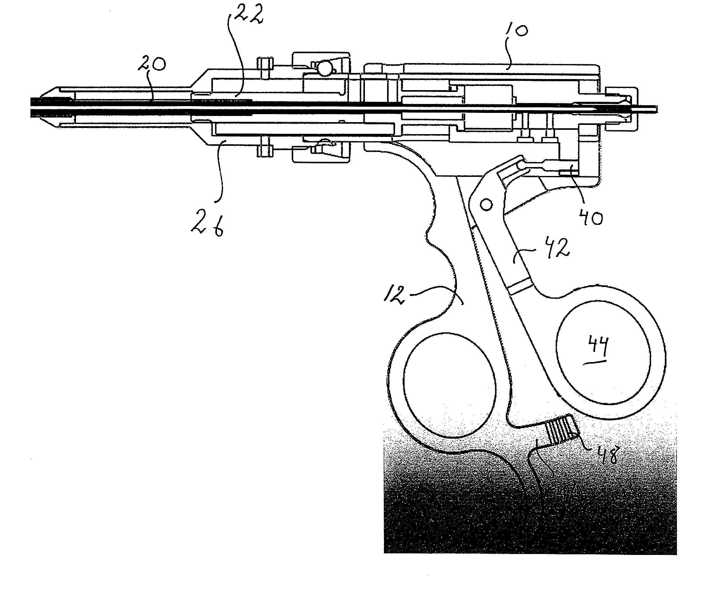
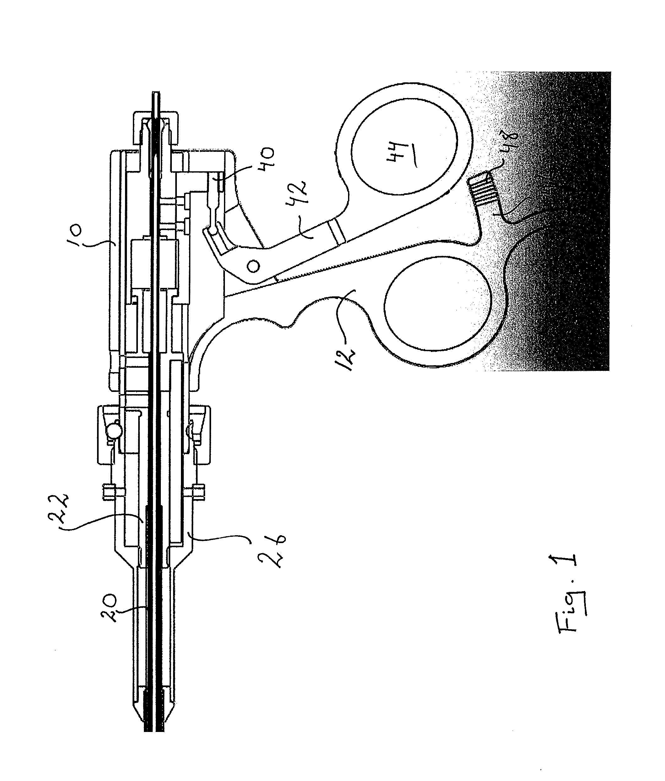
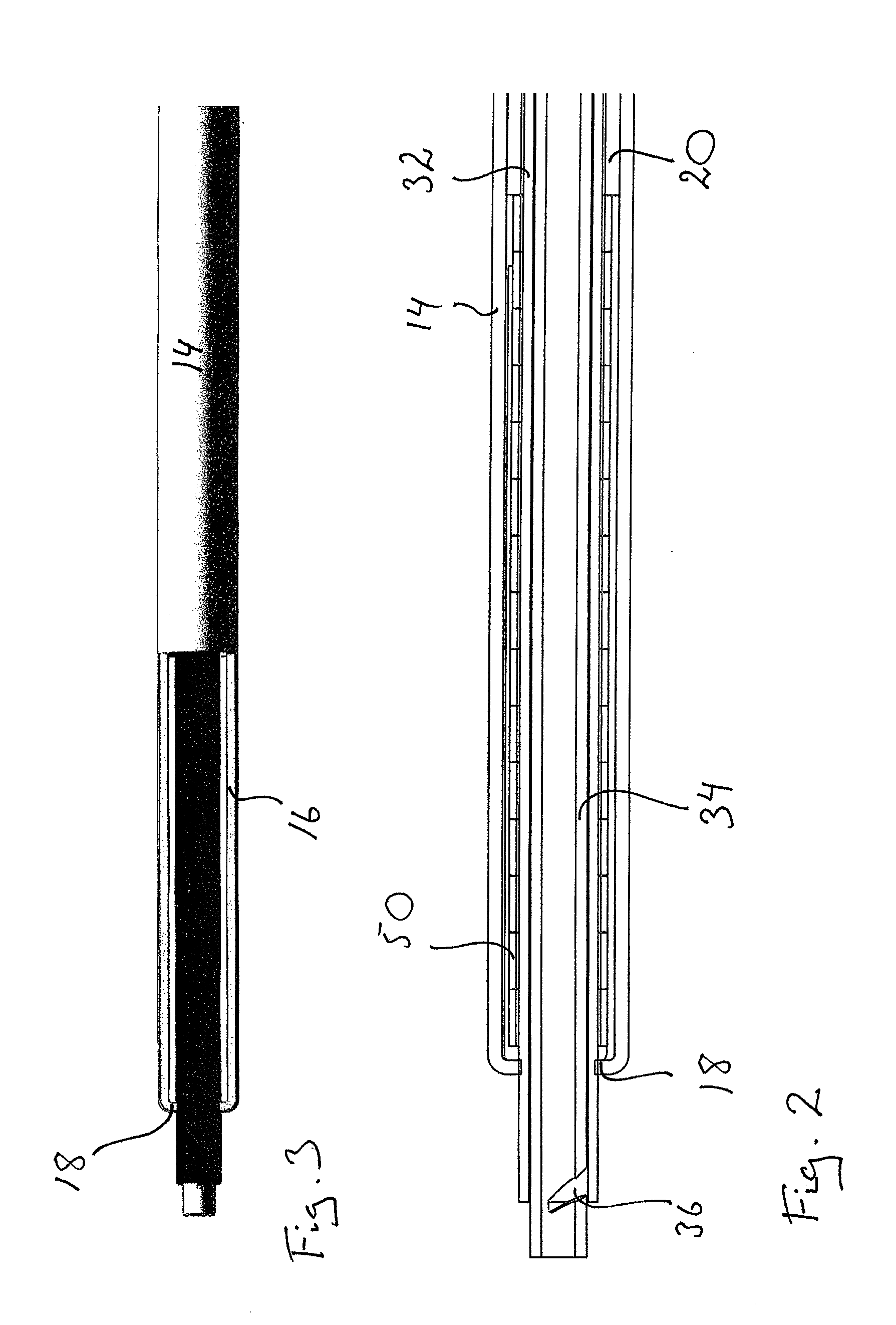
[0027]The instrument shown in the drawings comprises a generally tubular housing 10. A handle 12 is attached to the outer surface of the housing and shaped as to provide a grip for a user. At a proximal end of the housing a first tube 14, hereafter named guide tube, is attached. The proximal end of the guide tube 14 is arranged with longitudinally extending slits, forming arms 16 between the slits, FIG. 3, which arms are resilient in the radial direction. At the proximal end of the arms 16 inwardly directed ledges 18 are arranged. The function of th...


PUM


Abstract

A laparoscopic instrument includes a handle unit by which a user may hold the instrument, an elongated first tube attached to the handle unit, a second tube arranged slidable in relation to the first tube, that the second tube is provided with a thread gripping member capable of gripping suture threads, a locking member arranged to the tubes such that, when the second tube is moved in relation to the first tube, gripped suture threads are locked. The invention is characterised in that the device further includes storage elements for a number of rings, and a ring feeding member capable of, upon activation, moving the ring from the storage elements to a free position in which the suture threads run through the ring.

Description

TECHNICAL AREA[0001]The present invention relates to a laparoscopic instrument and in particular an instrument that facilitates the knotting of stitches in the interior of a patient.[0002]BACKGROUND OF INVENTION[0003]During a laparoscopic operation instruments with long handles are used in order to perform all steps of the operation. As a summary, the most important sewing-steps in a laparoscopic operation are the following: a first instrument holds the needle. The needle and the hanging thread are on one side of the tissues. With the help of the first instrument the needle is guided through the tissues that are to be sewn together. A second instrument receives the needle and then the first instrument releases the needle. The second instrument pulls the needle through the tissues so that the needle goes through from one side to a second side. The second instrument releases the needle and instead grips the thread at a suitable distance from the tissue on the second side. With suitabl...

Claims


Application Information

Patent Timeline
IPC IPC(8): A61B17/04
CPCA61B17/0487A61B17/0469A61B2017/0488
Inventor NAJAR, AZAD
Owner LAPROTECH
Why Eureka
Try Eureka